Liquid crystal display device

Inactive Publication Date: 2009-03-12
JAPAN DISPLAY CENT INC
View PDF8 Cites 6 Cited by
  • Summary
  • Abstract
  • Description
  • Claims
  • Application Information

AI Technical Summary

Benefits of technology

[0010]The present invention has been made in consideration of the above-described problem, and the object of the invention is to provide a liquid crystal display device to which an OCB mode is applied, wherein unwanted coloring of a screen is improved at a time of viewing the screen in an oblique direction. In addition, the object of the invention is to provide a liquid crystal display device to which an OCB mode is applied, wherein asymmetry of hue due to the direction of the viewing angle is improved and the display quality is good.
[0012]The present invention can provide a liquid crystal display device to which an OCB mode is applied, wherein unwanted coloring of a screen is improved at a time of viewing the screen in an oblique direction, and can provide a liquid crystal display device to which an OCB mode is applied, wherein asymmetry of hue due to the direction of the viewing angle is improved and the display quality is good.

Problems solved by technology

In the above-described OCB mode liquid crystal display device, there is a problem that the hue varies depending on the direction in which the screen is viewed.

Method used


Image

  • Liquid crystal display device
  • Liquid crystal display device
  • Liquid crystal display device

Examples


Embodiment Construction

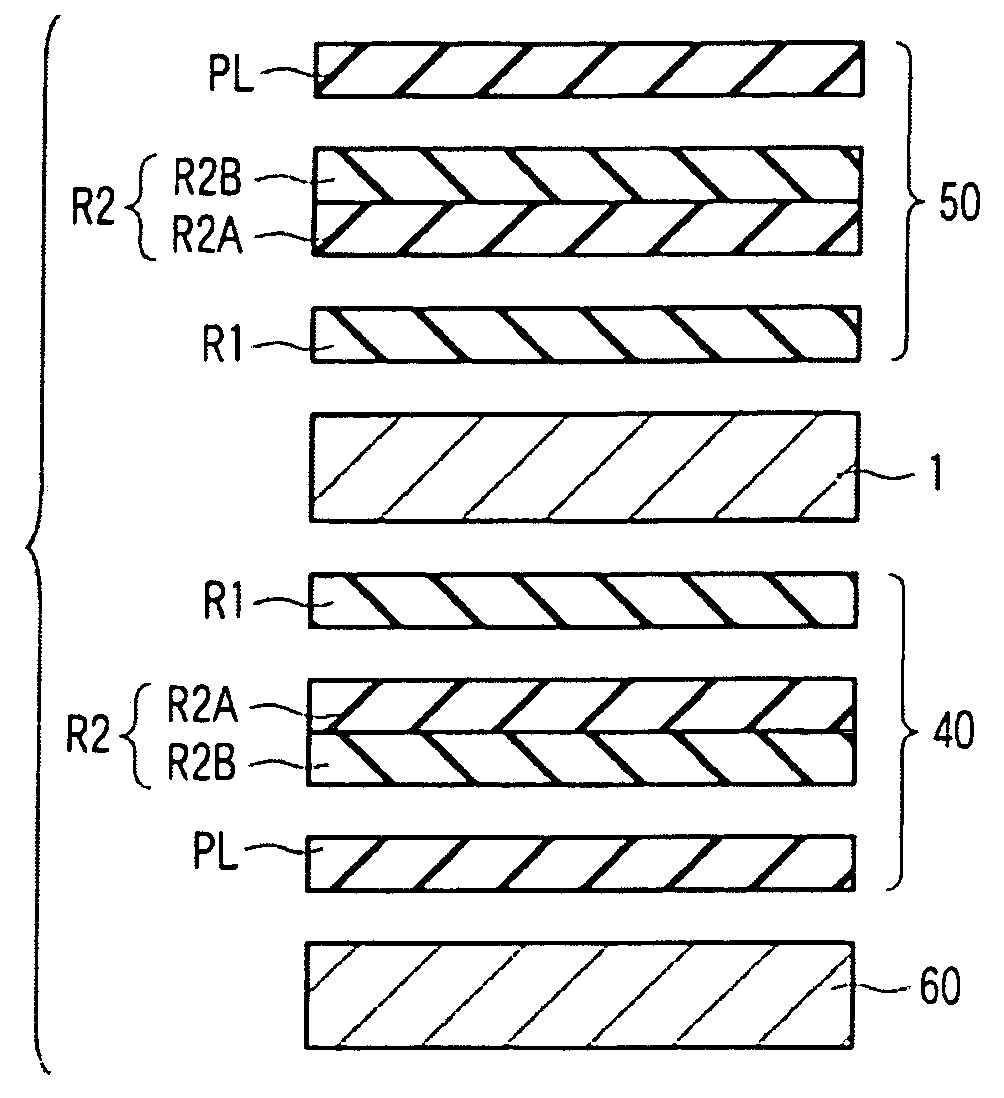
[0021]A liquid crystal display device according to an embodiment of the invention will now be described with reference to the accompanying drawings. A description is given of, as an example of the liquid crystal display device, a transmissive liquid crystal display device which is configured such that one pixel is composed of only a transmissive part that displays an image by selectively transmitting backlight. However, with use of other liquid crystal display devices to which an OCB mode is applied, such as a reflective liquid crystal display device which is configured such that one pixel is composed of only a reflective part that displays an image by selectively reflecting ambient light, and a transflective liquid crystal display device in which one pixel includes both a reflective part and a transmissive part, the same advantageous effects can be obtained on the basis of the embodiment which will be described below.

[0022]As shown in FIG. 1, the liquid crystal display device inclu...


PUM


Abstract

A liquid crystal display device includes a liquid crystal display panel to which an OCB mode is applied, and an optical compensation element which optically compensates a retardation of the liquid crystal layer in a predetermined display state in which a voltage is applied to the liquid crystal layer. The optical compensation element includes a polarizer, a first retardation plate which is disposed between the polarizer and the liquid crystal display panel and in which discotic liquid crystal molecules are fixed in a state in which the discotic liquid crystal molecules are hybrid-aligned along a normal direction, and a second retardation plate which is disposed between the polarizer and the first retardation plate and has wavelength dispersion characteristics which are opposite to wavelength dispersion characteristics of an in-plane retardation in the liquid crystal layer.

Description

CROSS REFERENCE TO RELATED APPLICATIONS[0001]This is a Continuation Application of PCT Application No. PCT / JP2008 / 054641, filed Mar. 13, 2008, which was published under PCT Article 21(2) in Japanese.[0002]This application is based upon and claims the benefit of priority from prior Japanese Patent Application No. 2007-063693, filed Mar. 13, 2007, the entire contents of which are incorporated herein by reference.BACKGROUND OF THE INVENTION[0003]1. Field of the Invention[0004]The present invention relates to a liquid crystal display device, and more particularly to a liquid crystal display device using an optically compensated bend (OCB) alignment technique which can realize a wide viewing angle and a high response speed.[0005]2. Description of the Related Art[0006]Liquid crystal display devices have been applied to various fields by taking advantage of their features such as light weight, small thickness and low power consumption.[0007]In recent years, attention has been paid to a liq...

Claims


Application Information

Patent Timeline
IPC IPC(8): G02F1/13363
CPCG02F1/13363G02F1/1395G02F2001/133637G02F2413/14G02F2413/105G02F2413/11G02F2413/13G02F2413/04G02F1/133637G02F1/133634
Inventor OKITA, MITSUTAKANISHIYAMA, KAZUHIROARAKI, SHIGESUMI
Owner JAPAN DISPLAY CENT INC
Why Eureka
Try Eureka