
Apparatus and method for restoring image

a technology of image and apparatus, applied in the field of image processing technique, can solve the problems of deterioration of focus, deterioration of image quality, and inability of sdaf method to ensure reliability for the operation of interpretation modules,

Active Publication Date: 2009-03-12
SAMSUNG ELECTRONICS CO LTD
View PDF2 Cites 18 Cited by
  • Summary
  • Abstract
  • Description
  • Claims
  • Application Information

AI Technical Summary

Benefits of technology

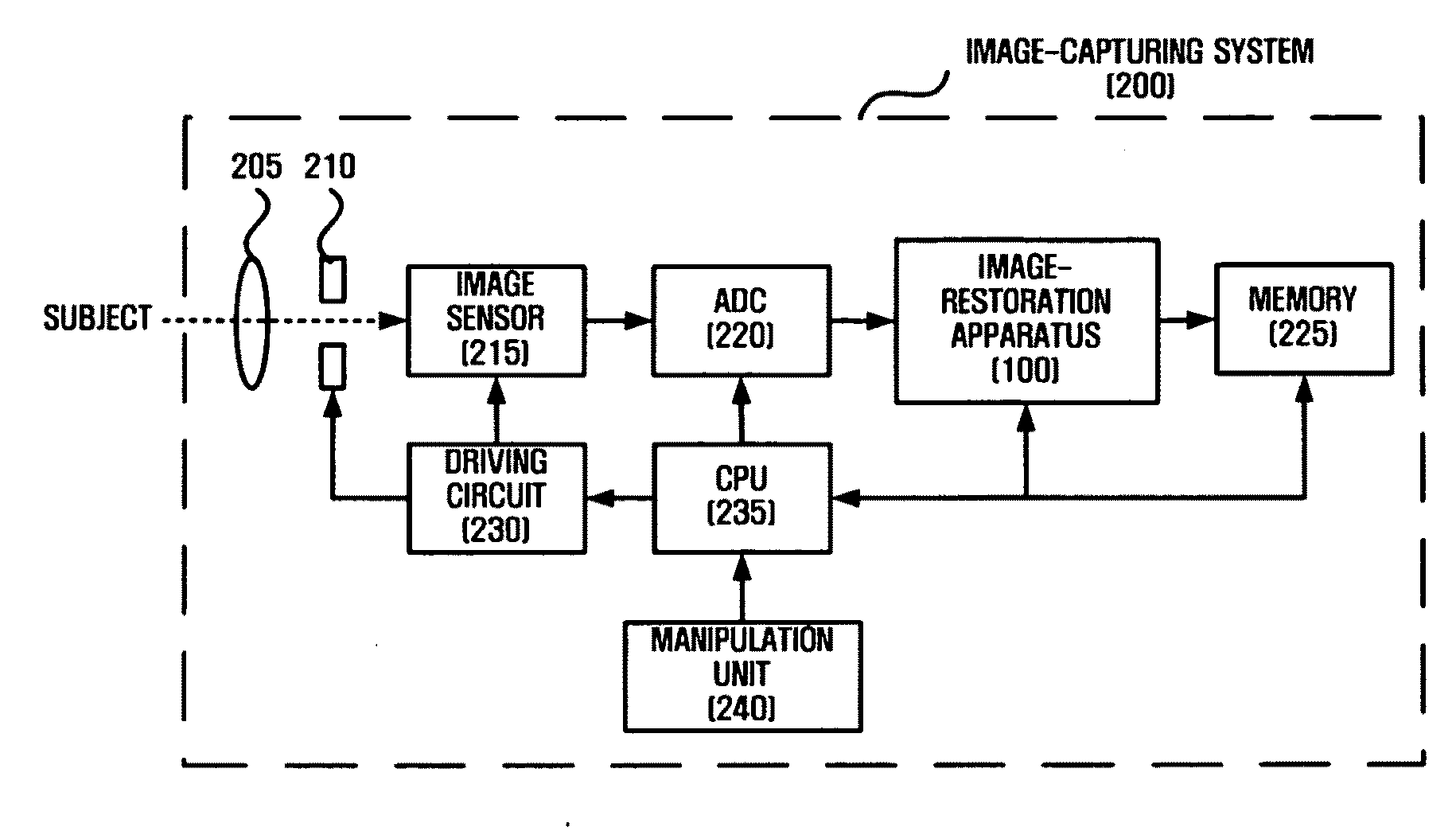
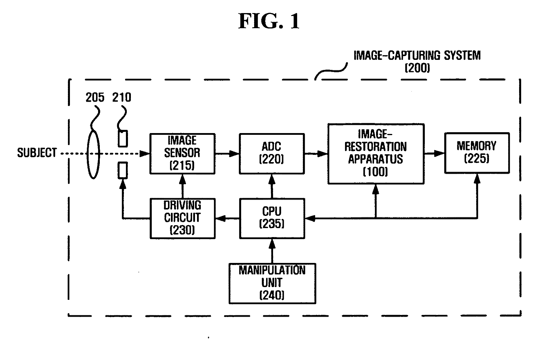
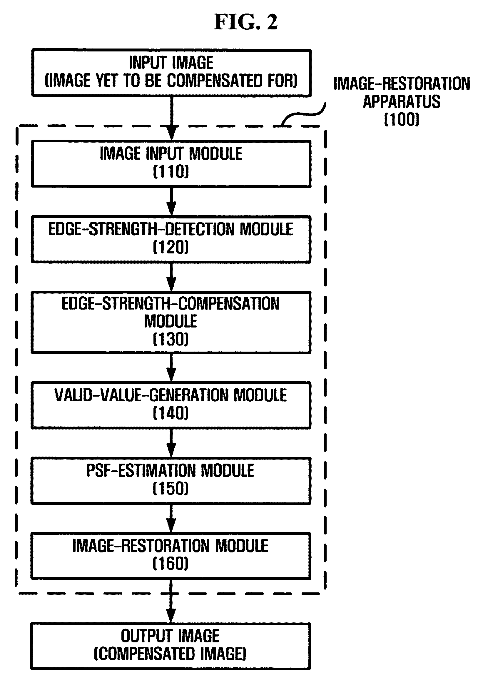
The present invention provides an apparatus and method for restoring an image by calculating valid values for different distance-specific blur levels, and determining which channel is sharpest based on the distance between the subject and the image sensor. The apparatus includes an edge-strength-detection module, an edge-strength-compensation module, a valid-value-generation module, a PSF-estimation module, and an image-restoration module. The method involves detecting edge strength, compensating for the edge strength, generating a valid value indicating a blur level, estimating a PSF, and restoring the image using the PSF. The technical effect of the invention is to improve the quality of images captured by removing blurs and restoring them to their original sharpness.

Problems solved by technology

A deterioration of focus caused by an imprecise adjustment of focal distance is one of the major causes of the deteriorating quality of pictures obtained by image-capturing devices.
However, the IRAF method and the SDAF method may not be able to ensure reliability for the operation of an interpretation module, and may require a motor driving module of a moving a lens under the control of a control module.
In addition, it is generally time consuming to obtain an in-focus image using the IRAF method or the SDAF method.
This method, however, may result in errors caused by an input image having a complicated shape, or due to noise.
Also, this method may not be able to estimate a PSF corresponding to a distance-specific blur level.
However, the above-mentioned blur estimation methods may all result in errors, especially when an input image has a complicated shape.
Also, the above-mentioned blur estimation methods may not be able to estimate a PSF corresponding to a distance-specific blur level, even though they are able to determine the relative differences between the blur levels of channels.

Method used


Image

  • Apparatus and method for restoring image
  • Apparatus and method for restoring image
  • Apparatus and method for restoring image

Examples


example1

Example1>[-1-1-1-18-1-1-1-1]Example2>[0-10-14-10-10]LaplacianFilter,Equation(1)

[0044]Once the R-channel edge strength, the G-channel edge strength, and the B-channel edge strength are detected from the input image 121 in the above-mentioned manner, an R-channel edge map 123, a G-channel edge map 125, and a B-channel edge map 127 respectively representing the R-channel edge strength, the G-channel edge strength, and the B-channel edge strength are generated. The R-channel edge strength, the G-channel edge strength, and the B-channel edge strength are determined according to the distance between a subject of the input image and the image sensor 215.

[0045]Referring to FIG. 2, the edge-strength-compensation module 130 is provided with the R-channel edge strength, the G-channel edge strength, and the B-channel edge strength, which are all detected by the edge-strength-detection module 120. Then, the edge-strength-compensation module 130 compensates for the R-channel edge strength and the...


PUM


Abstract

An apparatus and method for restoring an image are provided. The apparatus includes an edge-strength-detection module which detects an R-channel edge strength, a G-channel edge strength and a B-channel edge strength from an input image and generates an R-channel edge map, a G-channel edge map and a B-channel edge map based on the R-channel edge strength, the G-channel edge strength and the B-channel edge strength; an edge-strength-compensation module which compensates for the R-channel edge strength and the B-channel edge strength based on the G-channel edge strength; a valid-value-generation module which generates a valid value indicating a blur level based on the compensated R-channel edge strength and the compensated B-channel edge strength; a point spread function (PSF) estimation module which estimates a PSF corresponding to the valid value; and an image-restoration module which restores the input image using the PSF.

Description

CROSS-REFERENCE TO RELATED APPLICATIONS[0001]This application claims priority from Korean Patent Application No. 10-2007-0092745 filed on Sep. 12, 2007 in the Korean Intellectual Property Office, the disclosure of which is incorporated herein by reference in its entirety.BACKGROUND[0002]1. Field[0003]One or more embodiments of the present invention relate to an image-processing technique, and, more particularly, to an apparatus and method for restoring an image in which a valid value corresponding to a distance between a subject of an input image and an image sensor is calculated based on a red (R)-channel edge strength, a green (G)-channel edge strength and a blue (B)-channel edge strength of the input image, and it is determined which of R, G and B channels is sharpest based on the valid value and a point spread function (PSF), corresponding to whichever of the R, G and B channels is determined to be sharpest.[0004]2. Description of the Related Art[0005]A deterioration of focus ca...

Claims


Application Information

Patent Timeline
Patent Type & Authority Applications(United States)
IPC IPC(8): H04N5/208G06K9/40H04N23/40
CPCH04N5/208H04N5/142
Inventor LIM, JAE-GUYNKANG, JOO-YOUNGOK, HYUN-WOOKLEE, SEONG-DEOK
Owner SAMSUNG ELECTRONICS CO LTD
Learn More