
Vertical actuator having a gravity compensation device

a technology of gravity compensation and actuator, which is applied in the direction of supporting/enclosing/casing, mechanical energy handling, electrical equipment, etc., can solve the problems of low position of the movable part, the actuator, and the mass of the actuator, so as to achieve the effect of reducing the number of actuators

Inactive Publication Date: 2009-03-12
ETEL SA
View PDF11 Cites 10 Cited by
  • Summary
  • Abstract
  • Description
  • Claims
  • Application Information

AI Technical Summary

Benefits of technology

[0011]Example embodiments of the present invention eliminate or at least reduce the disadvantages mentioned above by providing a vertical actuator whose movable part, upon absence of a current supply, has a position of stable equilibrium which corresponds to a high or upper position of the movable part, a positive resultant force being ensured over the entire functional range of the actuator, such that in response to the absence of a current supply, the movable part is able to reach the position of stable equilibrium from any position of the functional range provided.

Problems solved by technology

One problem with vertical actuators is that the movable part, which includes the load that is assigned to the actuator, has a certain mass and therefore is subject to gravity.
In most practical applications, a low position of the movable part which, e.g., has a tool at its lower end, when the actuator is stationary, that is, when it is no longer supplied with electric current, is very unfavorable.
First of all, a relatively bulky, additional device is needed for the weight-compensation function.
Such a system is thus relatively complex and costly.
Therefore, the area below the spindle is obstructed by the compressed-air device which is disposed at the lower end of the cylinder in which the central spindle of the movable part moves.
Consequently, the movable part is unable to bear a load at the bottom of the central spindle.
This seriously limits the practical applications to be considered.
In certain instances, this can cause damage to the tool or to the product being produced at the moment, which is situated under this tool.

Method used


Image

  • Vertical actuator having a gravity compensation device
  • Vertical actuator having a gravity compensation device
  • Vertical actuator having a gravity compensation device

Examples


Embodiment Construction

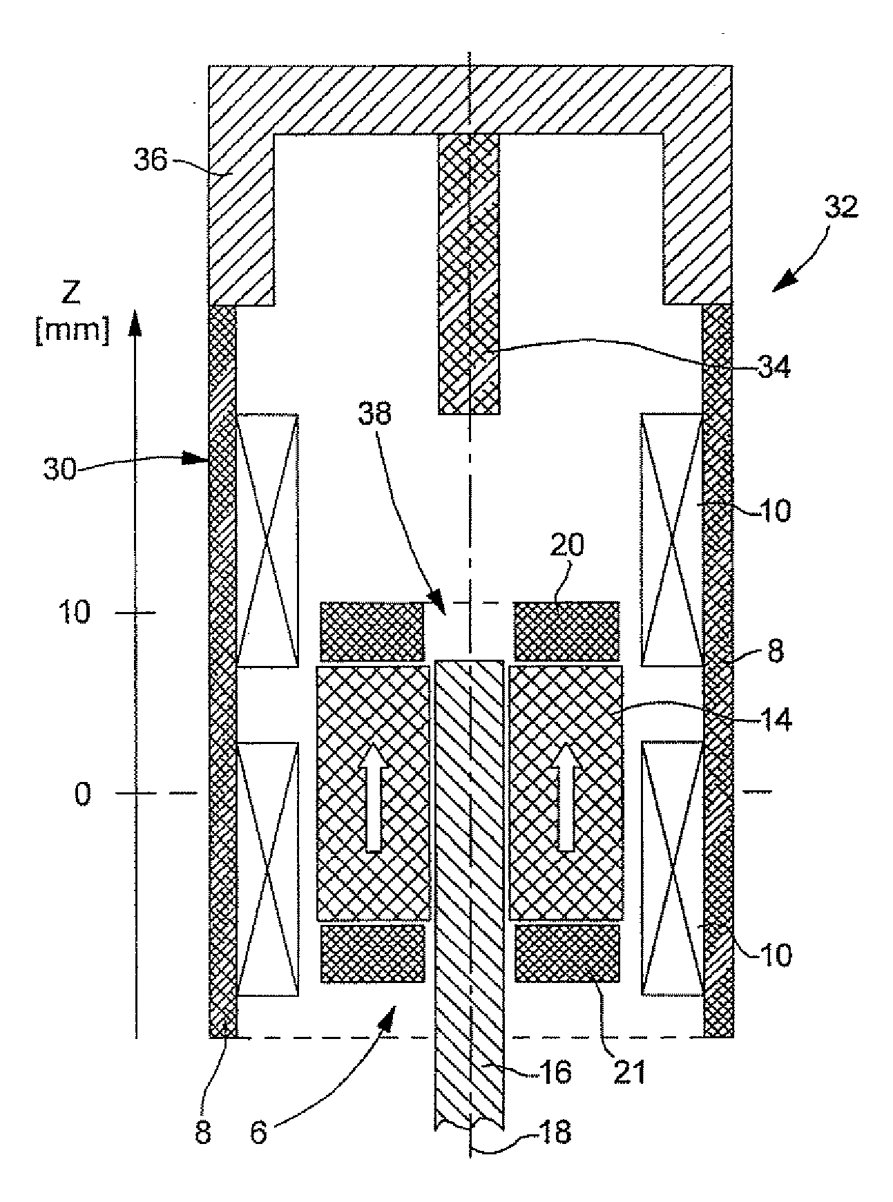
[0028]In the following, a vertical actuator according to an example embodiment of the present invention is described with reference to FIGS. 3 to 5. The reference numerals which have already been described in detail before in connection with the actuator in FIG. 1 are not all described again here in detail.

[0029]Vertical actuator 32 includes an upper part 34 made of magnetic material arranged above movable part 6. Upper part 34 is a component of stationary part 30 of actuator 32. Part 34 is supported by a part 36 made of non-magnetic material. The part 36 forms a cover for the actuator, e.g., part 36 joins upper magnetic part 34 to magnet yoke 8. However, part 36 magnetically separates upper magnetic part 34 and magnet yoke from each other. Upper magnetic part 34 is thus magnetically isolated from yoke 8.

[0030]In this example embodiment, upper magnetic part 34 is formed by a metal pin whose axis coincides with central axis 18 of movable part 6. Other forms and special configurations...


PUM


Abstract

A vertical actuator has a stationary part that includes an upper part made of magnetic material which is magnetically separated from a yoke which bears a coil. The upper magnetic part generates an overall reluctance force on the movable part of the actuator which, over the entire functional range of the actuator, is slightly greater than the gravitational force. When the coil is not energized, the movable part has a position of stable equilibrium which is in the upper section of this functional range.

Description

CROSS-REFERENCE TO RELATED APPLICATIONS[0001]The present application claims priority to Application No. 01419 / 07, filed in the Swiss Confederation on Sep. 10, 2007, which is expressly incorporated herein in its entirety by reference thereto.FIELD OF THE INVENTION[0002]The present invention relates to a vertical actuator equipped with device for the compensation of gravity or gravitational force.[0003]For example, the vertical actuator is formed by a linear motor whose movable part shifts vertically. This movable part includes at least one permanent magnet, and the stationary part of the actuator includes a magnet yoke bearing at least one coil. A coil should be understood to be a coil or any winding disposed such that it generates a magnetic field when supplied with electric current. The actuator may be single-phase or multiphase.BACKGROUND INFORMATION[0004]One problem with vertical actuators is that the movable part, which includes the load that is assigned to the actuator, has a c...

Claims


Application Information

Patent Timeline
IPC IPC(8): H02K41/00
CPCH02K33/12H02K7/106H02K33/16
Inventor CARDON, VINCENT
Owner ETEL SA
Learn More