
Air intake manifold for coupling the output of a compressor to the air intake of an internal combustion engine

a technology for air intake manifolds and internal combustion engines, which is applied in the direction of machines/engines, combustion-air/fuel-air treatment, bends, etc., can solve the problems of stock manifolds deficient in several aspects, preventing the engine from achieving optimum performance, and less than optimum performance, so as to improve engine performance, increase air flow, and use the effect of engine operating power rang

Active Publication Date: 2009-03-12
ADVANCED FLOW ENG
View PDF1 Cites 18 Cited by
  • Summary
  • Abstract
  • Description
  • Claims
  • Application Information

AI Technical Summary

Benefits of technology

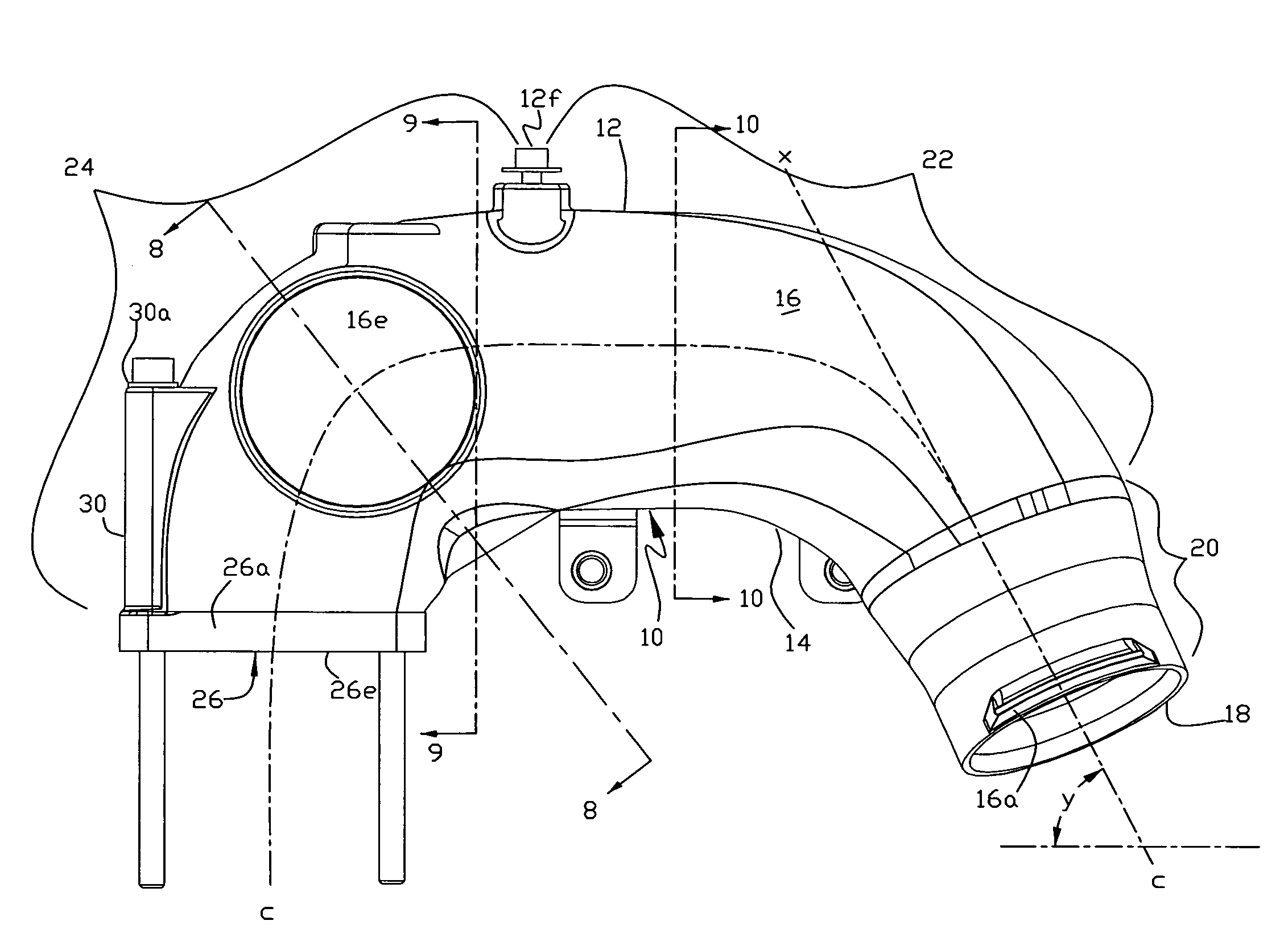
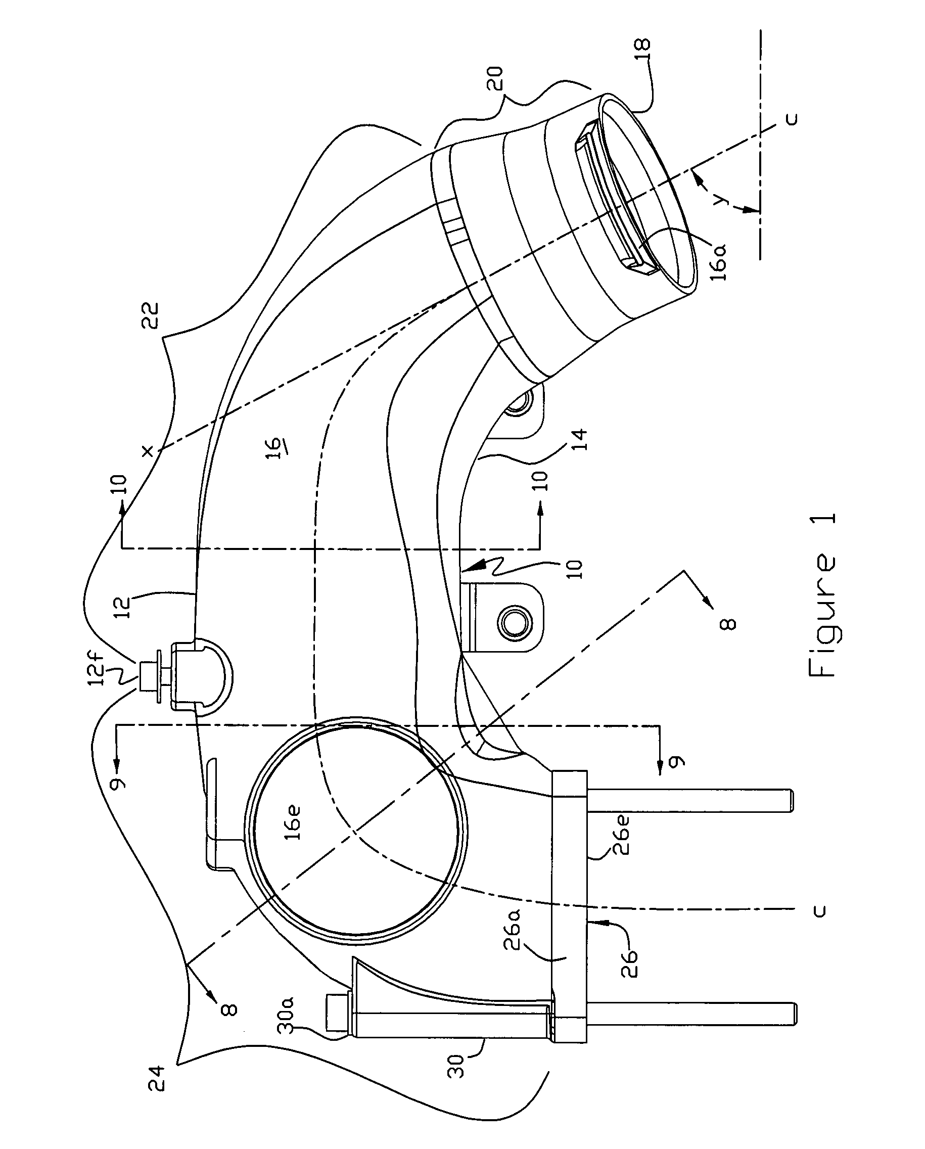
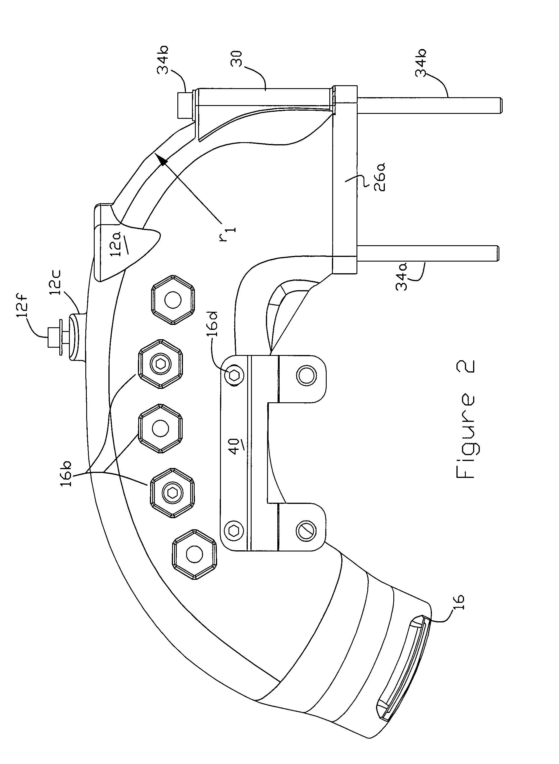
[0014]An aftermarket air flow coupler for connecting the outlet of a compressor, such as a turbocharger, to an internal combustion engine's air intake, in accordance with the present invention, is in the form of an elongated tubular manifold having a top, bottom and side walls. The manifold progresses from an upstream end defining a circular intake port, to a relatively short, generally straight proximal section, adapted to connect to the intake port to the turbocharger outlet, then to a sweeping compound curved central section, then to a section forming a generally 90° bend terminating in a generally rectangular discharge end defining a generally planar outlet port with a proximal side closest to the upstream end and a distal side remote from the upstream end. The manifold includes mounting screw receptacles forming apertured screw head retaining seats positioned along the proximal and distal sides of the outlet through which mounting screws may be inserted to secure the manifold to the engine's air intake. The seats positioned adjacent the proximal side are located in the interior of the manifold to optimize the size of the outlet port and provide an increased effective inner radius at the bend. Preferably the bottom wall, through the 90° bend, is in the form of an inclined plane further increasing the effective radius of the bottom wall through the bend. At least one, and preferably two, evenly spaced distal air flow turning vanes are positioned within the distal section with the vanes having a curvature comparable to the curvature of the distal section. The vanes promote uniform velocity distribution across the cross-section and downstream of the bend, thereby optimizing the flow rate.
[0016]The improvement in air flow of the invention versus the stock unit was measured using a predetermined pressure differential, e.g., 1.5″ H20 across the manifold with the result that the invention provides about a 30% improvement in air flow at that pressure differential which would represent a very useful operating power range for the engine. Specifically at this pressure differential the stock unit experienced an air flow of about 155 ftt3 / min versus the manifold of the invention of about 206 ft3 / min. The increased air flow to the engine will result in improved engine performance and better fuel mileage under the same driving conditions.

Problems solved by technology

Original equipment manufactured (“OEM”) manifolds for channeling air flow between a compressor, such as a turbocharger outlet and the air intake of an internal combustion engine frequently provide less then optimum fluid flow characteristics thereby preventing the engine from achieving optimum performance.
The stock manifold was (and still is) deficient in several aspects, e.g., in providing a limited cross-sectional area for air flow and in its mounting arrangement for securing the outlet end to the engine air intake plate.
The latter deficiency results from the pinched-in-sides of the manifold adjacent the outlet end which accommodate the two manifold / engine air intake mounting screws closest to the turbocharger (“proximal mounting screws”).
The 90° bend presents a challenge, particularly where (as in the case with the stock unit) the radius of the bottom (or inner) wall is considerably smaller than the radius of the top (or outer) wall at the bend.
The resulting seat accommodating recesses, though smaller than the pinched-in-sides of the stock version, and the proximal mounting screws shafts extending inside the manifold still create a significant flow restriction resulting in less than optimum performance.
The screw shafts as well as the inwardly protruding seats (to form a pleasing outside appearance) interrupt and impede the air flow resulting in less than optimum performance.
Moreover, plastic (while perhaps providing less restriction to air flow) is a relative poor thermal conductor as compared to aluminum.

Method used


Image

  • Air intake manifold for coupling the output of a compressor to the air intake of an internal combustion engine
  • Air intake manifold for coupling the output of a compressor to the air intake of an internal combustion engine
  • Air intake manifold for coupling the output of a compressor to the air intake of an internal combustion engine

Examples


Embodiment Construction

[0025]Referring now to FIGS. 1-7, a preferred embodiment of the intake manifold 10 is in the form of a cast aluminum elongated tubular member having a top (upper), bottom (lower), and side walls 12, 14, and 16, respectively, formed in three principal sections starting at the upstream end defining a circular intake port 18 adapted to be connected to the outlet of a tubrocharger intercooler (not shown) via a conventional hose and clamp (not shown). Outwardly projecting ribs 16a serve to maintain the hose and clamp in place on the manifold once installed. The upstream end progresses to a short, generally straight, proximal section 20 (e.g., about 1″-3″ in length), thence to a sweeping curved central section 22 and finally to a more pronounced curved distal section 24 forming a 90° bend and terminating in a downstream end 26 surrounded by a peripheral rim 26a enclosing a generally rectangular outlet or discharge opening or port 28 (FIG. 4). By way of example only, the radius (r1) of the...


PUM

PropertyMeasurementUnit
Angleaaaaaaaaaa
Radiusaaaaaaaaaa
Heightaaaaaaaaaa

Abstract

An elongated air intake manifold, for coupling a compressor outlet to the air intake of an internal combustion engine, includes bottom, top and side walls progressing from a circular upstream end through a sweeping curved central section to a 90° bend section terminating in a peripheral rim surrounding an air outlet port. The peripheral rim has opposed proximal and distal sides and a lower surface facing the engine air intake opening. A pair of proximal and distal mounting screw receptacles are formed integrally with and located on the interior and exterior of the manifold, respectively, for receiving mounting screws to secure the manifold to the engine. Preferably, the proximal mounting screw receptacles are arranged so that the heads of the mounting screws extend a minimum distance into the manifold interior. Optionally, one or more turning vanes may be positioned in the bend section interior of the manifold.

Description

FIELD OF THE INVENTION[0001]The present invention relates to intake manifolds and more particularly to an aftermarket air intake manifold for connecting the output of a compressor, such as a turbocharger, to the air intake of an internal combustion engine.BACKGROUND OF THE INVENTION[0002]Original equipment manufactured (“OEM”) manifolds for channeling air flow between a compressor, such as a turbocharger outlet and the air intake of an internal combustion engine frequently provide less then optimum fluid flow characteristics thereby preventing the engine from achieving optimum performance.[0003]An example of such sub-optimal performance is the OEM or stock intake manifold for the 2003-2007 Dodge Ram Commonrail® engine trucks utilizing tubrocharged Cummins® 5.9L diesel engines. The Dodge® stock intake manifold, as installed in the engine compartment, is shown in the digital photograph identified and attached as item 1 to the Information Disclosure Statement (IDS) submitted herewith. ...

Claims


Application Information

Patent Timeline
IPC IPC(8): F02M35/104
CPCF02B27/00Y02T10/144F02M35/10032F02M35/10078F02M35/10144F02M35/10163F02M35/1017F02M35/10209F02M35/10262F02M35/10275F02M35/10321F02M35/10354F02M35/104Y02T10/146F02M35/10019F02B27/005Y02T10/12
Inventor NIAKAN, SHAHRIAR NICKMIYAGISHIMA, STUART T.NGUYEN, JACK T.
Owner ADVANCED FLOW ENG
Learn More