Rolling tool with integrated drawing stage

Inactive Publication Date: 2009-02-26
MASCHFAB MULLER WEINGARTEN AG
View PDF18 Cites 9 Cited by
  • Summary
  • Abstract
  • Description
  • Claims
  • Application Information

AI Technical Summary

Benefits of technology

[0008]The invention is based on the object of developing a method and a tool in which both the forming of a blank to produce a raw piece and the forming on the raw piece by ro

Problems solved by technology

The disadvantage of the method is that a raw piece that has been preformed to be close to contour has to be already available before the rolling procedure.
A further disadvantage in the embodiment described above is in the structural design of the profiling roller support by means of the support rollers.
Although this embodiment renders possible a profiling roller diameter of reduced size, it is structurally very complex and cost-intensive because of the arrangement of the support rollers.
In addition, the tool has a large overall height as a result.

Method used


Image

  • Rolling tool with integrated drawing stage
  • Rolling tool with integrated drawing stage
  • Rolling tool with integrated drawing stage

Examples


Embodiment Construction

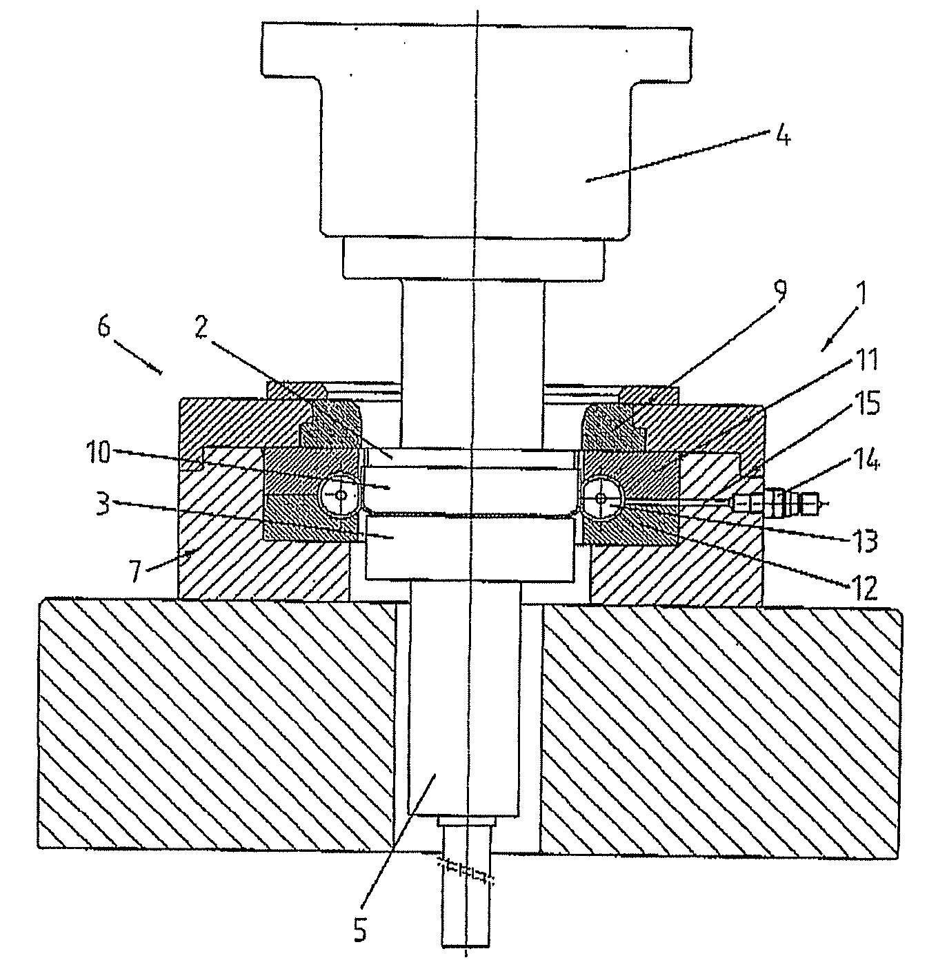
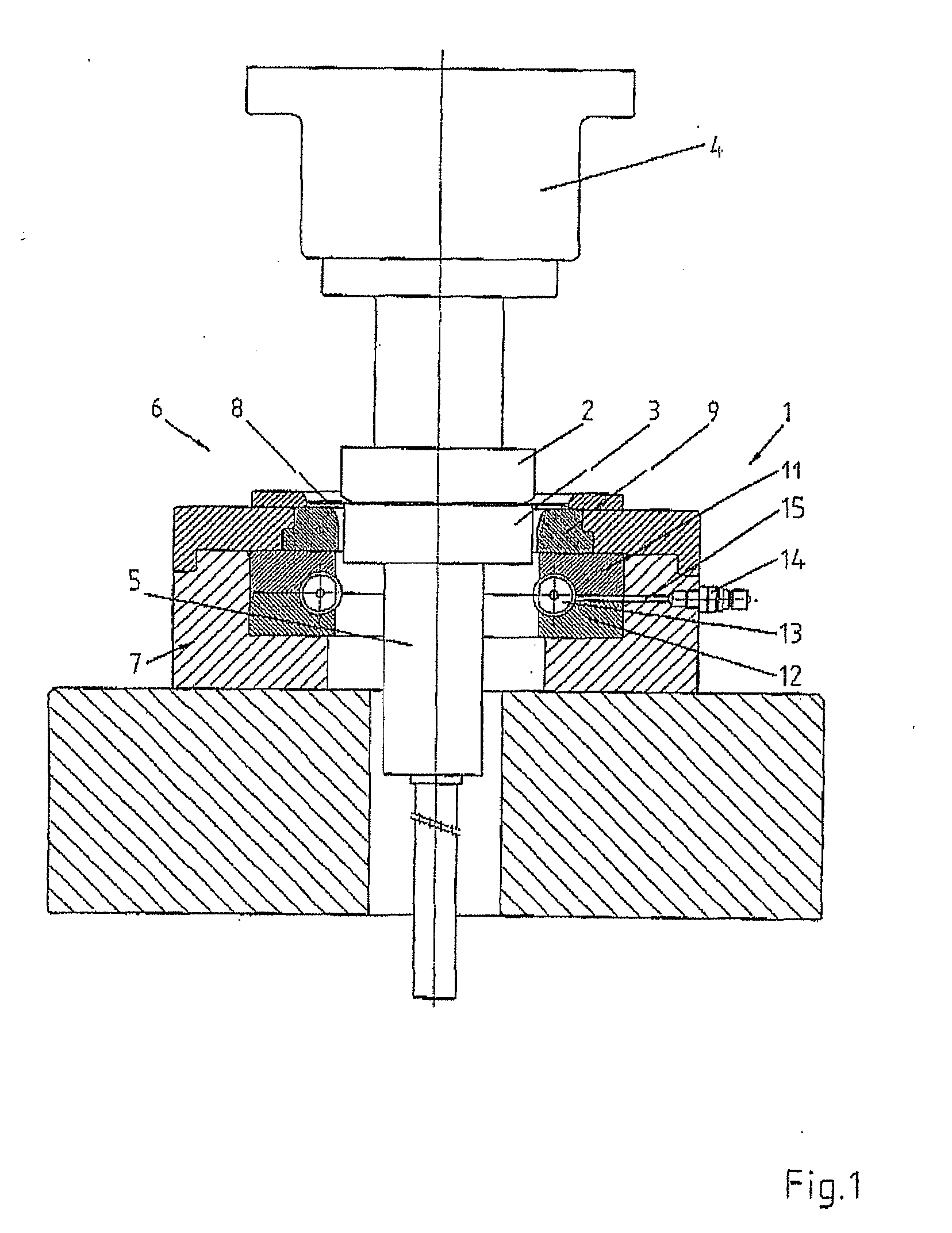
[0015]FIG. 1 shows a sectional representation of the tool 1 according to the invention. The tool 1 consists of a drawing unit 6 and a rolling unit 7. The drawing unit 6, in turn, consists of a die upper part 2, which is fixedly connected to the ram 4, and of a die lower part 3, which can be moved vertically via the lifting unit 5.

[0016]FIG. 1 shows the position at the start of the drawing operation. The ram 4, with the die lower part 2, has already moved downwards to such an extent that the forming of the blank 8 can commence. In this case, the blank 8 is drawn downwards via the drawing ring 9. The die upper part 3 is displaced downwards. Owing to the contour of the die upper part 2 and the design of the drawing ring 9, after the drawing operation there is produced a raw piece 10 which serves as a basic form for the subsequent operation of forming by rolling.

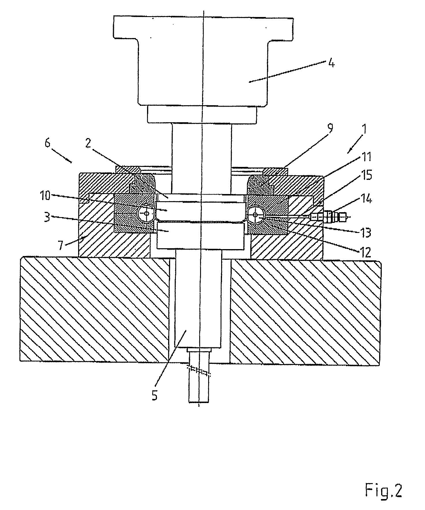
[0017]FIG. 2 shows a position during the operation of forming by rolling. It shows the rolling unit 7, with the upper bearing ...


PUM

PropertyMeasurementUnit
Forceaaaaaaaaaa
Circumferenceaaaaaaaaaa

Abstract

The invention relates to a method and a tool for producing cylindrical workpieces having longitudinal grooves, wherein the actual rolling operation is preceded by a drawing stage integrated in the tool and wherein the forming rollers are realized with an improved mounting.

Description

CROSS REFERENCE TO RELATED APPLICATIONS [0001]This application is a continuation of International Application No. PCT / DE2007 / 000264, filed Feb. 9, 2007, which designated the United States, and claims the benefit under 35 USC §119(a)-(d) of German Application No. 10 2006 007 501.3 filed Feb. 16, 2006, the entireties of which are incorporated herein by reference.FIELD OF THE INVENTION [0002]The invention relates to a rolling method and a tool for producing cylindrical workpieces having longitudinal grooves, by means of forming rollers having an improved mounting. In addition, the actual rolling operation is to be optionally preceded by a drawing stage integrated in the tool.BACKGROUND OF THE INVENTION [0003]In the production of profiled pieces such as, for example, clutch disk-carriers, toothed-belt disks or similar workpieces having a basic cylindrical structure, high levels of accuracy and precision are frequently required. In particular, accuracy and the surface quality are importa...

Claims


Application Information

Patent Timeline
IPC IPC(8): B21D17/04B21B13/08
CPCB21D22/28B21D15/02
Inventor SCHLAYER, DIETMARPIEPERHOFF, HANS-JOACHIMBEIG, FRANKZIESEL, NORBERT
Owner MASCHFAB MULLER WEINGARTEN AG
Why Eureka
Try Eureka