
Pipe cutting tool

a pipe cutter and tool technology, applied in the field of tools used for cutting pipes, can solve the problems of pipe cutters being unusable, difficult to use, and devices suffering from certain significant limitations,

Inactive Publication Date: 2009-02-26
WILLIAMS DENNIS R
View PDF9 Cites 19 Cited by
  • Summary
  • Abstract
  • Description
  • Claims
  • Application Information

AI Technical Summary

Benefits of technology

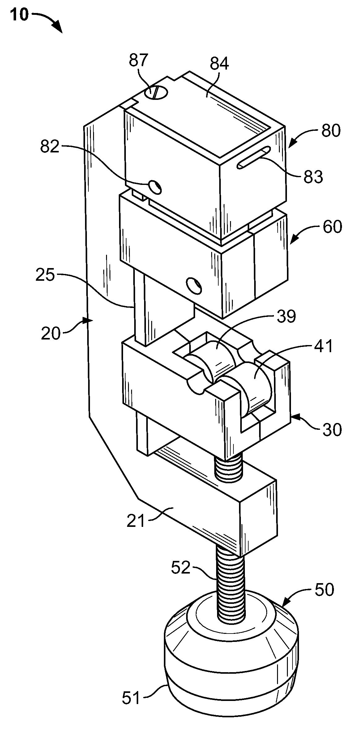
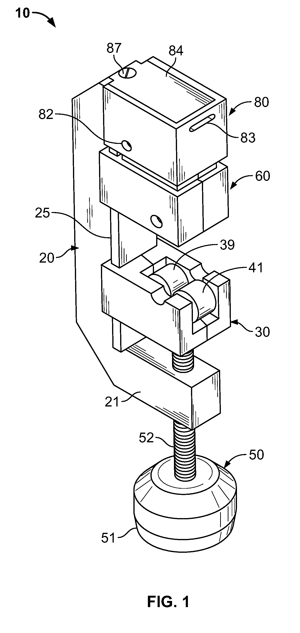
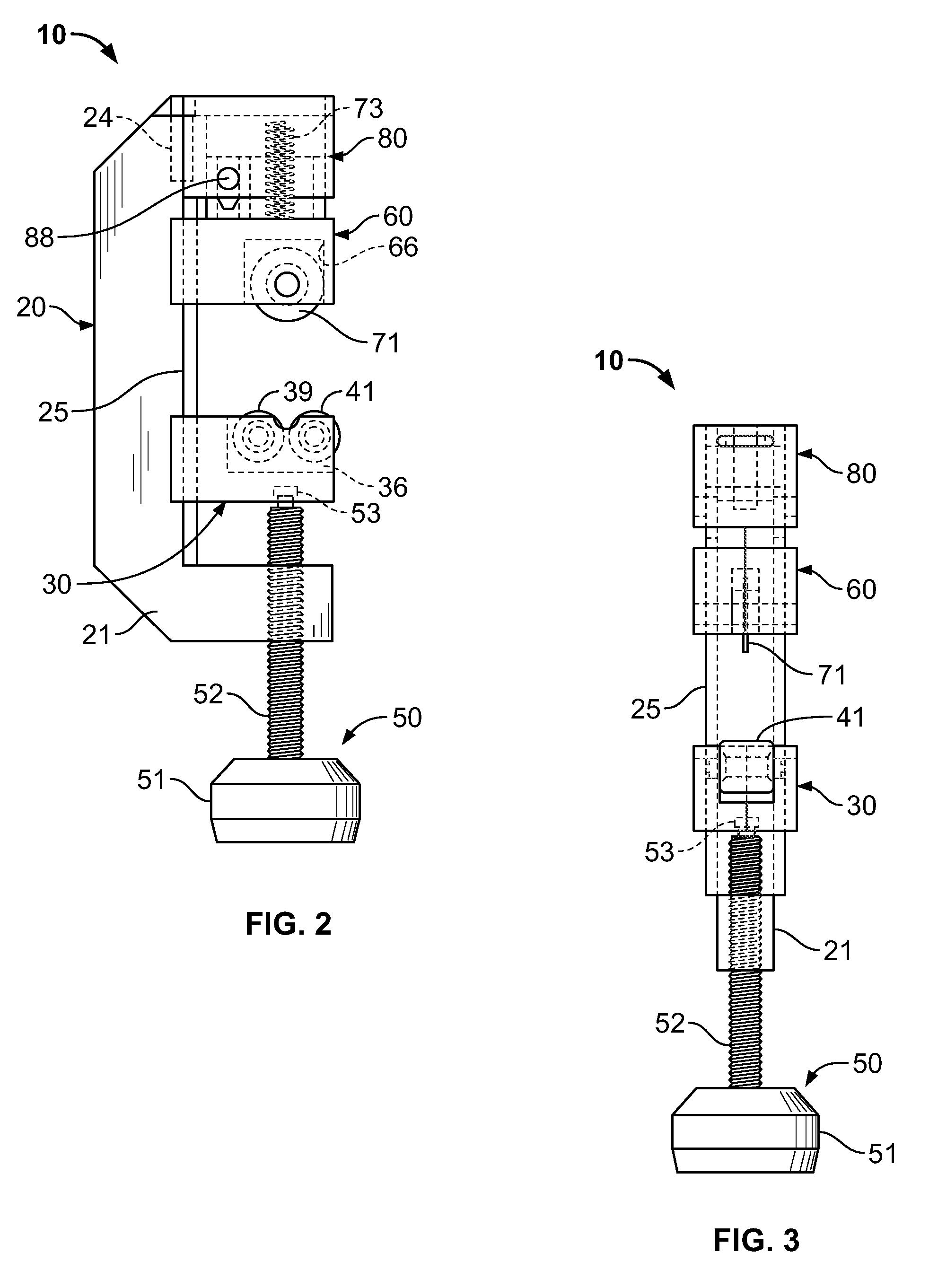
[0006]In accordance with one aspect of the present invention, a pipe-cutting system is provided. This pipe-cutting system includes a tool having body having a rear portion, a middle portion, and a front portion; a track attached to or formed integrally with the middle portion of the body; a first moveable carriage slidably mounted on the track, wherein the first moveable carriage further includes a first roller and a second roller mounted therein; a handle mounted in the rear portion of the body, wherein the handle is connected to the first moveable carriage, and wherein turning the handle in one direction causes the first moveable carriage to travel toward the rear portion of the body and turning the handle in the opposite direction causes the first moveable carriage to travel toward the front portion of the body; a second moveable carriage slidably mounted on the track, wherein the second moveable carriage further includes a rotatable cutting blade mounted therein, and wherein the rotatable cutting blade is adapted to cooperate with the first and second rollers to receive and cut a length of pipe; a carriage stop mounted on or formed integrally with on the front portion of the body, wherein the carriage stop is adapted to receive therein a portion of the second moveable carriage; and a biasing member mounted between the carriage stop and the second moveable carriage, wherein the biasing member exerts substantially continuous force on the second moveable carriage for urging the rotatable cutting blade against a pipe being cut.
[0007]In accordance with another aspect of the present invention, a pipe-cutting tool is provided. This pipe-cutting tool includes a rigid body having a rear portion, a middle portion, and a front portion; a track attached to or formed integrally with the middle portion of the body; a first moveable carriage slidably mounted on the track, wherein the first moveable carriage further includes a first housing, and wherein a first roller and a second roller are rotatably mounted in the first housing; a handle mounted in the rear portion of the body, wherein the handle is connected to the first moveable carriage, and wherein turning the handle in one direction causes the first moveable carriage to travel toward the rear portion of the body and turning the handle in the opposite direction causes the first moveable carriage to travel toward the front portion of the body; a second moveable carriage slidably mounted on the track, wherein the second moveable carriage further includes a second housing and wherein a rotatable cutting blade is mounted in the second housing, and wherein the rotatable cutting blade is adapted to cooperate with the first and second rollers to receive and cut a length of tubing or pipe; a carriage stop mounted on or formed integrally with on the front portion of the body, wherein the carriage stop is adapted to receive therein a portion of the housing of the second moveable carriage; and a biasing member mounted between the carriage stop and the second moveable carriage, wherein the biasing member exerts substantially continuous force on the second moveable carriage for urging the rotatable cutting blade against a pipe being cut.
[0008]In yet another aspect of this invention, a method for cutting a length of tubing or pipe is provided. This method includes providing a cutting tool such as those described above; inserting a length of tubing or pipe into the cutting tool between the first and second rollers and the rotatable cutting blade; turning the handle to tighten the first moveable carriage against the length of tubing or pipe; rotating the entire cutting tool around the length of tubing or pipe to engage the rotatable cutting blade; and continuing to rotate the cutting tool until the rotatable cutting blade has cut completely through the length of tubing or piping.

Problems solved by technology

While pipe cutters such as the second type described above are generally effective for their intended purpose, these devices suffer from certain significant limitations.
These design aspects make such pipe cutters unwieldy, difficult to use, and in some cases may result in damage to the area of the pipe that is being cut.
Damage to an area of pipe is particularly problematic when only a short length of pipe is available for cutting and subsequently attaching an item (e.g., a compression connector) thereto.

Method used


Image

  • Pipe cutting tool
  • Pipe cutting tool
  • Pipe cutting tool

Examples


Embodiment Construction

[0015]Exemplary embodiments of the present invention are now described with reference to the Figures. Reference numerals are used throughout the description to refer to the various elements and structures. Although the following description contains many specifics for the purposes of illustration, a person of ordinary skill in the art will appreciate that many variations and alterations to the following details are also within the scope of the invention. Accordingly, the following embodiments of the invention are set forth without any loss of generality to, and without imposing limitations upon, the claimed invention.

[0016]The present invention relates to a device for use in cutting lengths of metal or plastic pipe or tubing. As previously indicated, a first general embodiment of this invention provides a pipe-cutting system; a second general embodiment of this invention provides a pipe cutting tool; and a third general embodiment of this invention provides a method for cutting a le...


PUM

PropertyMeasurementUnit
lengthaaaaaaaaaa
forceaaaaaaaaaa
areaaaaaaaaaaa

Abstract

A pipe-cutting tool is provided. This tool includes a body; a track on the middle portion of the body; a first moveable carriage mounted on the track, wherein the first carriage includes first and second rollers mounted therein; a handle mounted in the rear portion of the body, wherein the handle is connected to the first moveable carriage; a second moveable carriage slidably mounted on the track, wherein the second moveable carriage further includes a rotatable cutting blade mounted therein; a carriage stop mounted on or formed integrally with on the front portion of the body, wherein the carriage stop is adapted to receive therein a portion of the second moveable carriage; and a biasing member mounted between the carriage stop and the second moveable carriage, wherein the biasing member exerts substantially continuous force on the second moveable carriage for urging the rotatable cutting blade against a pipe being cut.

Description

CROSS-REFERENCE TO RELATED APPLICATIONS[0001]This patent application claims the benefit of U.S. Provisional Patent Application Ser. No. 60 / 956,759 filed on Aug. 20, 2007 and entitled “Pipe Cutter,” the disclosure of which is incorporated by reference as if fully rewritten herein.BACKGROUND OF THE INVENTION[0002]The present invention relates generally to tools used for cutting pipes, and more particularly to a “spring-loaded” pipe cutter that includes mechanical means for exerting substantially continuous force on certain portions of the pipe cutter for facilitating use thereof.[0003]A pipe cutter is a common type of tool used by plumbers and other workers to cut pipe, tubing, conduit, and the like. Besides producing a generally clean cut, the pipe cutter is often a faster and more convenient way of cutting pipe than using a hacksaw. There are two basic types of pipe cutters. Plastic tubing cutters, which typically resemble a pair of pruning shears, may be used for thinner pipes and ...

Claims


Application Information

Patent Timeline
Patent Type & Authority Applications(United States)
IPC IPC(8): B23D21/06B26D1/00
CPCB23D21/08Y10T83/04
Inventor WILLIAMS, DENNIS
Owner WILLIAMS DENNIS R
Learn More