Speaker device

Inactive Publication Date: 2009-02-19
MASUDA TADASHI
View PDF6 Cites 31 Cited by
  • Summary
  • Abstract
  • Description
  • Claims
  • Application Information

AI Technical Summary

Benefits of technology

[0025]As described above, the present invention provides a speaker device in which a pair of enhanced walls is disposed on a front face of a baffle board to pass by left and right sides of the radiating faces of a reference speaker and speakers other than the reference speaker, vertically extend along the front face of the baffle board and open left and right toward forward, and the radiated sound from the reference speaker is enhanced by the pair of enhanced walls. Therefore, the sound pressure enhancement effect on the radiated sound from the reference speaker can be obtained as in a case of a full-sized horn based on the horn theory.
[0026]The radiated sounds from all the speakers are radiated into an inside space of the pair of enhanced walls. Therefore, even though a woofer and a speaker for high frequency range are closely disposed above and below the reference speaker and each location of sound sources of the speakers is adjusted in a fore-and-aft direction to equalize each of arrival times of the radiated sounds, the radiated sounds from speakers for high and low frequency ranges can be radiated into a listening space without hitting the horn of a speaker for middle frequency range and being distorted as in a conventional horn-type speaker device.
[0027]Further, in the conventional horn-type speaker device, since the speakers for high, middle, and low frequency ranges are disposed outside openings of the respective horns, the radiated sounds from each of the speakers tend to disperse and thereby become unrealistic. In contrast, in the present invention, since each speaker is closely disposed around a central portion inside the pair of enhanced walls and the radiated sounds from each of the speakers are mixed in the inside space of the pair of enhanced walls to be radiated into the listening space from the front end of the pair of enhanced walls, the radiated sounds from each of the speakers tend to gather together and thereby become realistic.
[0028]That is, in the speaker device of the present invention, sound pressure enhancement is obtained as in the horn-type speaker device, the arrival times of the radiated sounds from the woofer to the tweeter are aligned, and each of the speakers are closely disposed to achieve realistic acoustics. Further, there is a multiple advantage in which a compact and balanced appearance can be realized in addition to such excellent acoustic characteristics.
[0029]Also, enhancement suppression gaps are formed in the both side vicinities of the radiating face of the woofer to radiate the radiated sound from the woofer through outer vacancies into the listening space. Therefore, the radiated sound from the woofer can be prevented from being partially enhanced by the pair of enhanced walls and flat frequency characteristics of the woofer can be realized.
[0030]When the directivity widening gaps are formed in the both side vicinities of an opening of a horn of a horn-type tweeter to pass the radiated sound from the horn-type tweeter outside the pair of enhanced walls and radiate it into the listening space, directivity of the reproduced sound of the horn-type tweeter can be broadened.

Problems solved by technology

However, a horn-type woofer requires a huge horn.
This is because, when a sound source of each speaker is aligned in a fore-and-aft direction to eliminate differences between arrival times of sounds radiated from each speaker, a front-end of a long horn of a midrange speaker protrudes, the long horn of the midrange speaker being hit by sounds radiated from a short-horn speaker for high frequency range and a direct radiation type woofer, thereby causing distortion by reflection.
Also, the protruded horn of the midrange speaker makes an appearance of the whole speaker device unbalanced.
In any case, speaker systems having horn-type speakers except for a woofer overlook such a harmful effect.

Method used


Image

  • Speaker device
  • Speaker device
  • Speaker device

Examples


first embodiment

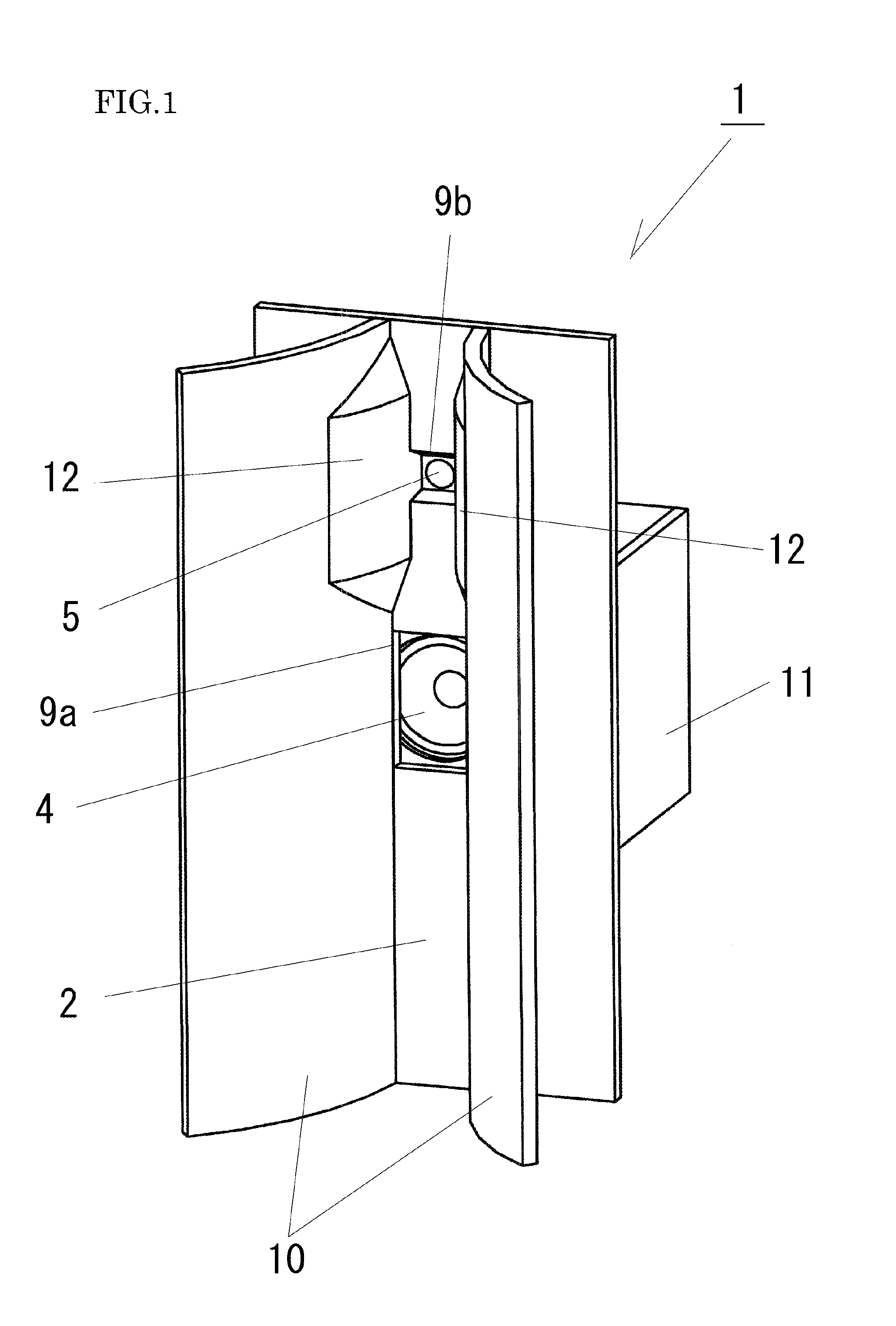
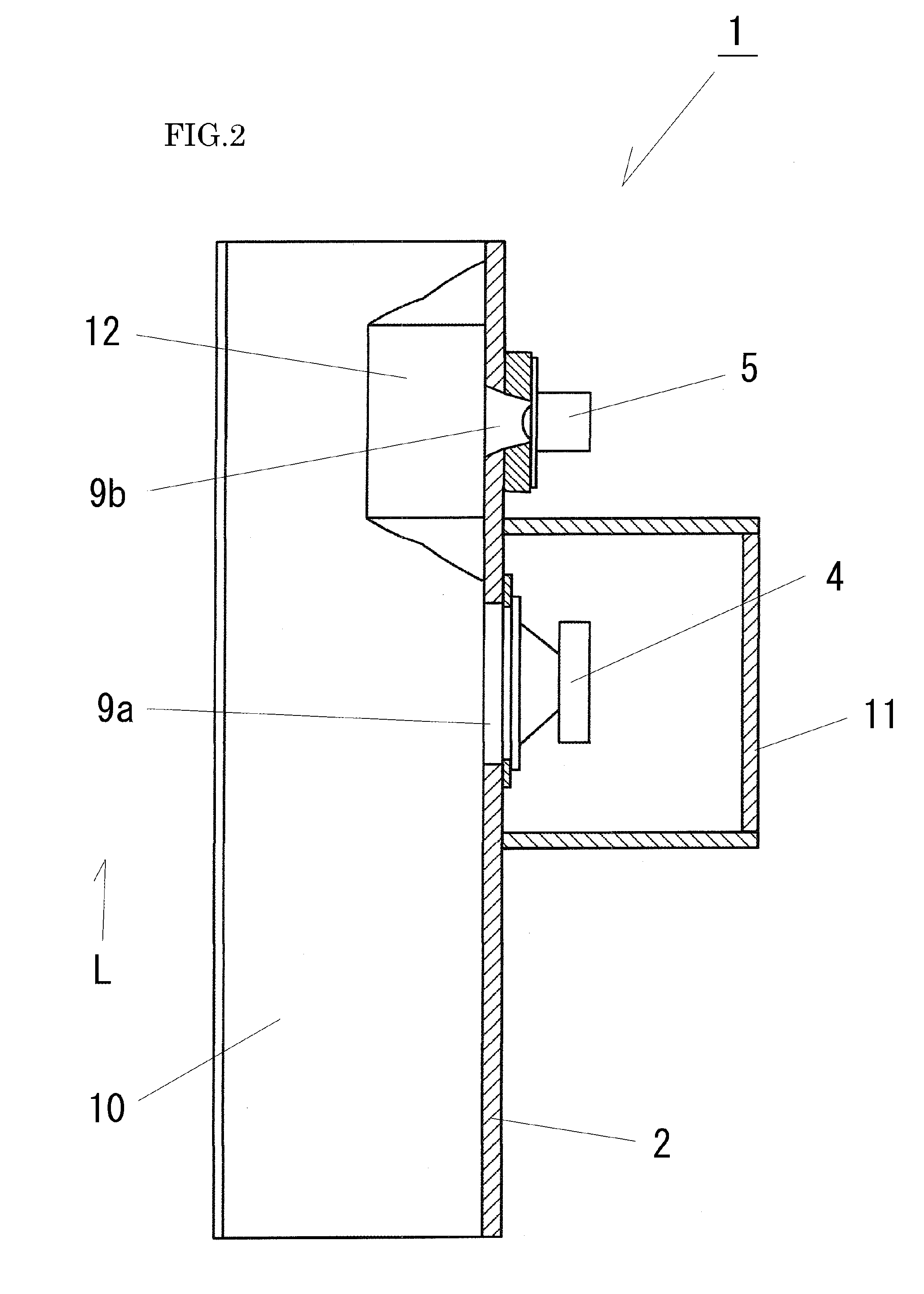
[0033]FIG. 1 is a perspective view of a speaker device 1 according to a first embodiment. The speaker device 1 includes two types of speaker respectively one for each type, a squawker 4 and a tweeter 5. The speaker device 1 is combined with another speaker device (not shown) including a woofer to constitute a three-way speaker system. That is, in the speaker device 1 of the first embodiment, the squawker 4 is a reference speaker according to the present invention.

[0034]As shown in FIGS. 1 to 4, the speaker device 1 according to the embodiment includes a rectangular baffle board 2. The baffle board 2 is made of plywood and its dimensions are: 40 cm (width)×82 cm (height)×18 mm (thickness). A rectangular opening 9a is formed in the middle of the baffle board 2. The squawker 4 is attached to the opening 9a from the back side. The squawker 4 is a corn-type full-range speaker in 18 cm diameter. The backside of the squawker 4 is surrounded by a closed-type cabinet 11 with an inner volume ...

second embodiment

[0051]FIG. 8 is a perspective view of a speaker device 1b according to a second embodiment. The speaker device 1b is configured such that apart of the speaker device 1 of the first embodiment is modified. Description of the common components will be omitted.

[0052]The speaker device 1b of this embodiment each includes three types of speaker, a woofer 3, a squawker 4, and a tweeter 5. The speaker device 1b constitutes a three-way speaker system by itself. That is, in the speaker device 1b of this embodiment, the squawker 4 is a reference speaker according to the present invention. The squawker 4 and the tweeter 5 incorporated in the speaker device 1b are same to those in the first embodiment. The woofer 3 is a cone-type speaker in 30 cm diameter.

[0053]The speaker device 1b includes a baffle board 2a, which is slightly longer than the baffle board in the first embodiment. The squawker 4 is positioned generally at a center on the backside face of the baffle board 2a, the tweeter 5 is po...

third embodiment

[0064]FIG. 14 is a perspective view of a speaker device 1c including a horn-type tweeter according to a third embodiment. The speaker device 1c is only different from the speaker device 1b of the second embodiment in term of the configuration around the attachment part of the tweeter. Thus, common components will be denoted in the same numerals and their description will be omitted.

[0065]In the speaker device 1c of this embodiment, a horn 17 instead of the pair of enhanced walls for high frequency range 12 is disposed on the front face of the baffle board 2a at the attachment part of the tweeter 5. The horn 17 is designed in a shape to enhance the radiated sound from the tweeter 5. The tweeter 5 is disposed behind a throat 9c of the horn 17. The tweeter 5 is a same one as in the first embodiment.

[0066]Left and right side plates 17b, 17c of the horn 17 are smoothly jointed with the inner wall surfaces of the pair of enhanced walls 10a. Accordingly, the radiated sound from the tweeter...


PUM


Abstract

To provide a speaker system in which arrival times of sounds radiated from each speaker are aligned, sound pressures of speakers other than a woofer are enhanced as in a horn-type speaker, and each speaker unit, which disperses with a conventional horn, is gathered to integrate functions of each speaker and present a balanced appearance.Two or more types of speakers 3, 4, 5 including a reference speaker 4 for reproducing a high frequency range next to a reproduction range of a woofer 3 are arranged in line and a pair of enhanced walls 10a is disposed on a front face of a baffle board 2 to pass by left and right sides of a radiating face of the reference speaker 4, vertically extend along the front face of the baffle board 2, and open left and right toward forward. Accordingly, the radiated sound from the reference speaker 4 is enhanced by an inside space of the pair of enhanced walls 10a without enhancing the radiated sound from the woofer 3.

Description

FIELD OF THE INVENTION[0001]The present invention relates to a speaker device in which two or more types of speaker with a different reproduction range are arranged in line on a baffle board.BACKGROUND ART[0002]A most typical speaker device having two or more types of speaker with a different reproduction range arranged in line on a baffle board includes three types of speaker respectively for high frequency range, middle frequency range, and low frequency range, which constitute a three-way speaker system. There are other speaker systems that constitute a four-way speaker system or more. Further, there is another speaker system including an additional speaker device having a speaker for reproducing the low frequency range.[0003]Generally, a speaker which constitutes a speaker system is called differently according to its reproduction range. In a three-way system, from a speaker of low frequency range, speakers are called woofer, squawker and tweeter. In a four-way system, from low ...

Claims


Application Information

Patent Timeline
IPC IPC(8): H04R25/00
CPCH04R1/24H04R2205/022H04R1/30
Inventor MASUDA, TADASHI
Owner MASUDA TADASHI
Why Eureka
Try Eureka