Measuring apparatus for power loss of magnetic device

a technology of measuring apparatus and magnetic device, which is applied in the direction of measurement device, power measurement by current/voltage, instruments, etc., can solve the problems of high cost of conventional measuring apparatus, increased cost of measuring apparatus, and detrimental to instrument and operator, so as to achieve low cost, loose measurement environment, and power loss of magnetic device

Inactive Publication Date: 2009-02-19
DELTA ELECTRONICS INC
View PDF4 Cites 4 Cited by
  • Summary
  • Abstract
  • Description
  • Claims
  • Application Information

AI Technical Summary

Benefits of technology

[0013]An object of the present invention is to provide a measuring apparatus for power loss of magnetic device with a low cost and loose measuring environment, while only a portion of the circuits within the measuring apparatus consumes power. Therefore, the inventive measuring apparatus can remove the drawback that the measuring apparatus consumes a great quantity of power during measurement, thereby reducing power loss. Moreover, the inventive measuring apparatus takes a shortened measuring period and is adapted for the quality control of magnetic devices without complicated measuring steps. Hence, the inventive measuring apparatus does not require a proficient operator to handle the measuring process.
[0014]To this end, a broader aspect of the present invention is associated with a measuring apparatus for power loss of magnetic device. The inventive measuring apparatus includes a power converter connected with a DC power supply and a magnetic device for converting a DC voltage supplied by the DC power supply into a rectangular wave alternating between positive and negative, so that the voltage across the magnetic device can be varied between positive and negative; a voltage measuring device connected in parallel with the DC power supply for measuring the input voltage of the power converter; and a current measuring device connected in parallel between the DC power supply and the power converter for measuring the input current of the power converter. The power loss of the magnetic device is substantially the product of the input voltage of the power converter and the input current of the power converter, and thus the measuring apparatus can obtain the power loss of the magnetic device by the product of the input voltage of the power converter and the input current of the power converter.

Problems solved by technology

1. High cost: Because a sophisticated sinusoidal wave generator 12, high-frequency amplifier 13 and measuring instruments 14 with a high bandwidth are used, the cost of the conventional measuring apparatus is high.
2. Strict measuring environment: Once the sophisticated measuring apparatus is employed, the measuring apparatus has to be operated under a specific temperature and humidity, which in turn increases the cost of the measuring apparatus.
3. Intense electromagnetic wave: When the sine wave or cosine wave sent by the sinusoidal wave generator 12 is amplified by the high-frequency voltage amplifier 13, an intense electromagnetic wave would be induced. The intense electromagnetic wave is detrimental to instrument and operator, and thus the cost of electromagnetic protection equipment has to be increased.
4. Large power consumption: The sinusoidal wave generator 12, the high-frequency voltage amplifier 13 and the measuring instrument 14 all need power to operate. The power loss of these elements during measurement will exceed the power loss of the magnetic device 11, and thereby causing additional power loss.
However, such measuring technique bears the following disadvantages:
1. Low measuring accuracy: The working temperature of the magnetic device 11 is limited, and thus the allowable temperature rise of the insulating medium 21 is limited.
Therefore, the measuring accuracy is relatively low.
Besides, the temperature of the insulating medium 21 within the thermal insulating container 23 is difficult to maintain uniform.
In this way, the measured temperature is different from location to location, and thus the measuring accuracy will be low.
Therefore, the measuring process is quite time-consuming.
3. Easy to cause human error: It is possible that each step of the measuring process would cause error, so the operator is required to possess proficient handling technique.

Method used


Image

  • Measuring apparatus for power loss of magnetic device
  • Measuring apparatus for power loss of magnetic device
  • Measuring apparatus for power loss of magnetic device

Examples


second embodiment

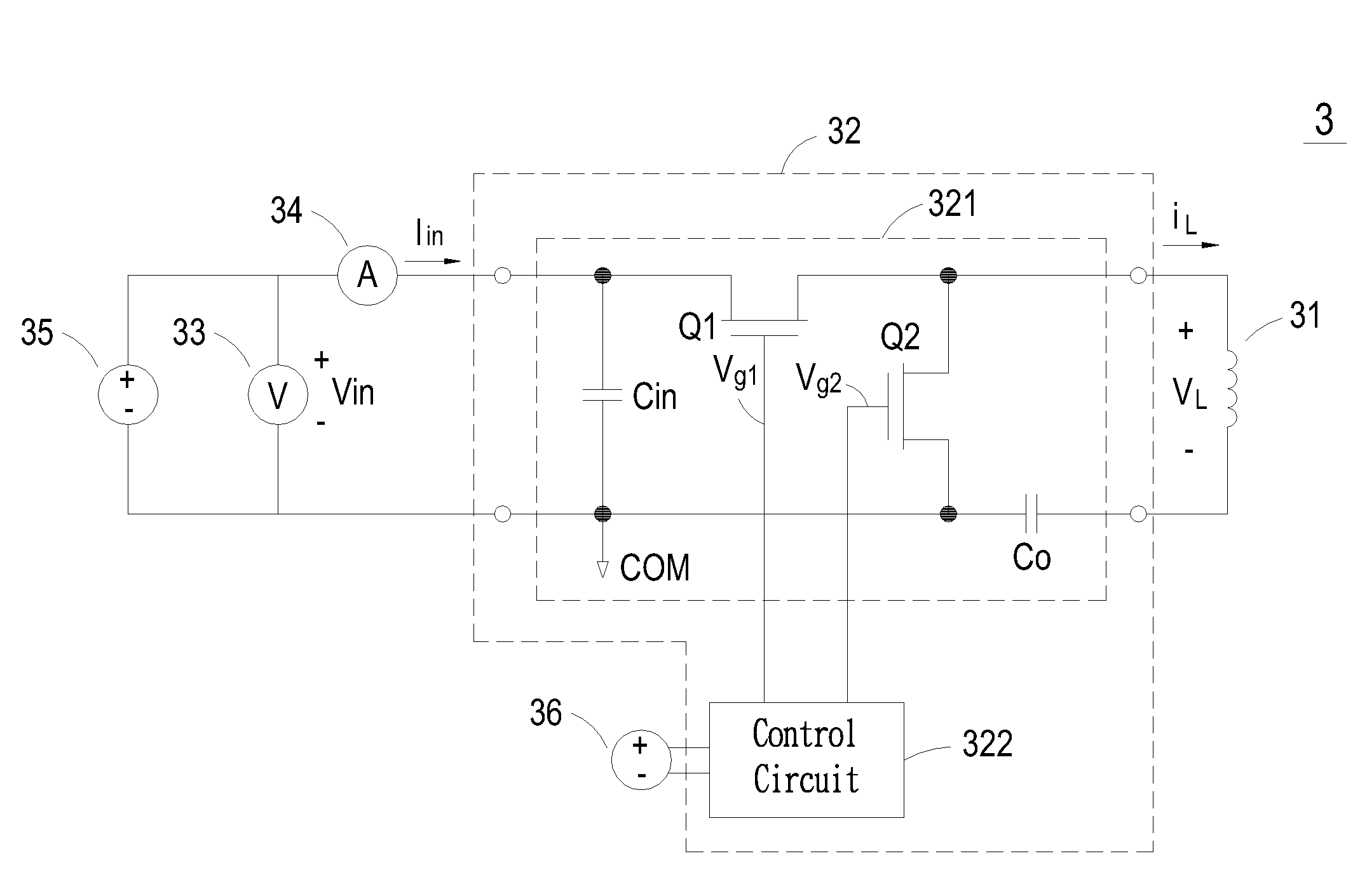
[0032]Referring to FIG. 5, the switch circuit within the measuring apparatus for power loss of magnetic device according to the present invention is shown. As shown in FIG. 5, the switch circuit 321 of the power converter 32 includes an input capacitor Cin, a first switch element Q1, a second switch element Q2, and an output capacitor Co, wherein each element has the same function and structure as the counterpart element disclosed in the previous embodiment. However, the output capacitor Co is connected between the first switch element Q1 and the output side of the power converter 32 in the present embodiment for filtering out the DC component of the output voltage, so that the voltage VL across the magnetic device 31 is a rectangular wave without any DC component. The current iL of the magnetic device 31 is a triangular wave as well, and the magnetic core of the magnetic device 31 will generate a corresponding triangular flux and cause power loss. Therefore, the power loss P of the...

third embodiment

[0033]Referring to FIG. 6, the switch circuit within the measuring apparatus for power loss of magnetic device according to the present invention is shown. As shown in FIG. 6, the switch circuit 321 of the power converter 32 includes an input capacitor Cin, a third switch element Q3, a fourth switch element Q4, a fifth switch element Q5, a sixth switch element Q6, and an output capacitor Co, wherein the input capacitor Cin is connected in parallel with the DC input side of the power converter 32 and a common node COM for filtering. The third switch element Q3 and the sixth switch element Q6 are connected in series with node A, and the other end of the third switch element Q3 and the other end of the sixth switch element Q6 are respectively connected to the first DC power supply 35. The fifth switch element Q5 and the fourth switch element Q4 are connected in series with node B, and the other end of the fifth switch element Q5 and the other end of the fourth switch element Q4 are res...

fifth embodiment

[0034]Referring to FIG. 8, the switch circuit within the measuring apparatus for power loss of magnetic device according to the present invention is shown. As shown in FIG. 8, the switch circuit 321 of the power converter 32 includes an input capacitor Cin, a third switch element Q3, a fourth switch element Q4, a fifth switch element Q5, a sixth switch element Q6, and a first capacitor C, wherein the input capacitor Cin is connected in parallel with the DC input side of the power converter 32 for filtering. The third switch element Q3 and the sixth switch element Q6 are connected in series with node A, and the other end of the third switch element Q3 and the other end of the sixth switch element Q6 are respectively connected to the first DC power supply 35 and the common node COM. The fifth switch element Q5 and the fourth switch element Q4 are connected in series with node B and then connected to the first capacitor C, and the other end of the fourth switch element Q4 and the other...


PUM


Abstract

A measuring apparatus for measuring power loss of magnetic device is disclosed. The measuring apparatus includes a power converter, a voltage measuring device and a current measuring device. The power converter is connected to the DC power supply and the magnetic device for converting the DC voltage supplied by the DC power supply into a rectangular wave alternating between positive and negative for use by the magnetic device. The voltage measuring device is connected in parallel with the DC power supply for measuring the input voltage of the power converter. The current measuring device is connected in series between the DC power supply and the power converter for measuring the input current of the power converter. The power loss of the magnetic device is substantially equal to the product of the input voltage and input current of the power converter.

Description

FIELD OF THE INVENTION[0001]The present invention is related to a measuring apparatus, and more particularly to a measuring apparatus for power loss of magnetic device.BACKGROUND OF THE INVENTION[0002]Magnetic devices, such as transformers or inductors, are important devices for a variety of electronic devices. The quality of the magnetic device can affect the operation and performance of electronic devices. Thus, it is important to measure the power loss of magnetic devices to acquire the accurate property of the magnetic devices.[0003]Referring to FIG. 1, the measuring apparatus for measuring the power loss of magnetic device according to the prior art is shown. As indicated in FIG. 1, the conventional measuring apparatus employs a sinusoidal wave to measure the power loss of a magnetic device 11. The conventional measuring apparatus shown in FIG. 1 includes a sinusoidal wave generator 12, a high-frequency voltage amplifier 13, and a measuring instrument 14. The principle for meas...

Claims


Application Information

Patent Timeline
Patent Type & Authority Applications(United States)
IPC IPC(8): G01R21/06
CPCG01R21/06
Inventor GUAN, JUN-FENGCHEN, WEIWU, YI-FAN
Owner DELTA ELECTRONICS INC
Why Eureka
Try Eureka