
Radiant coolers and methods for assembling same

a technology of radiant cooler and cylinder, which is applied in the direction of indirect heat exchangers, manufacturing tools, lighting and heating apparatus, etc., can solve the problems of increasing the overall size and cost of the gasification system

Active Publication Date: 2009-02-12
AIR PROD & CHEM INC
View PDF22 Cites 9 Cited by
  • Summary
  • Abstract
  • Description
  • Claims
  • Application Information

AI Technical Summary

Problems solved by technology

However, increasing the number of water-filled tubes also increases the overall size and cost of the gasification system.

Method used


Image

  • Radiant coolers and methods for assembling same
  • Radiant coolers and methods for assembling same
  • Radiant coolers and methods for assembling same

Examples


Embodiment Construction

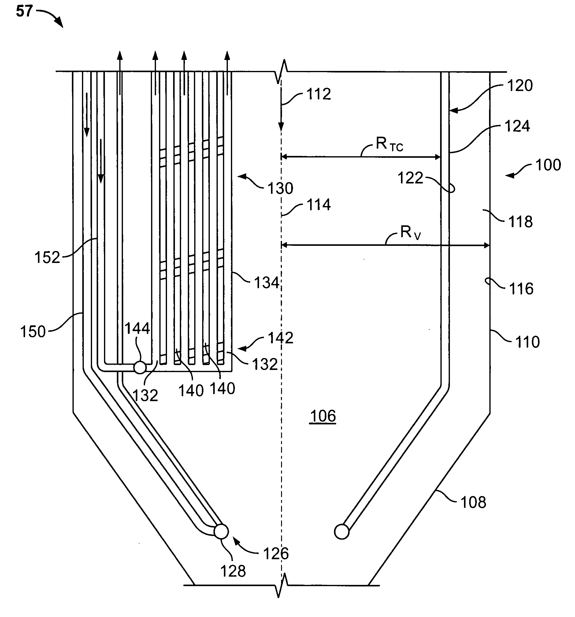
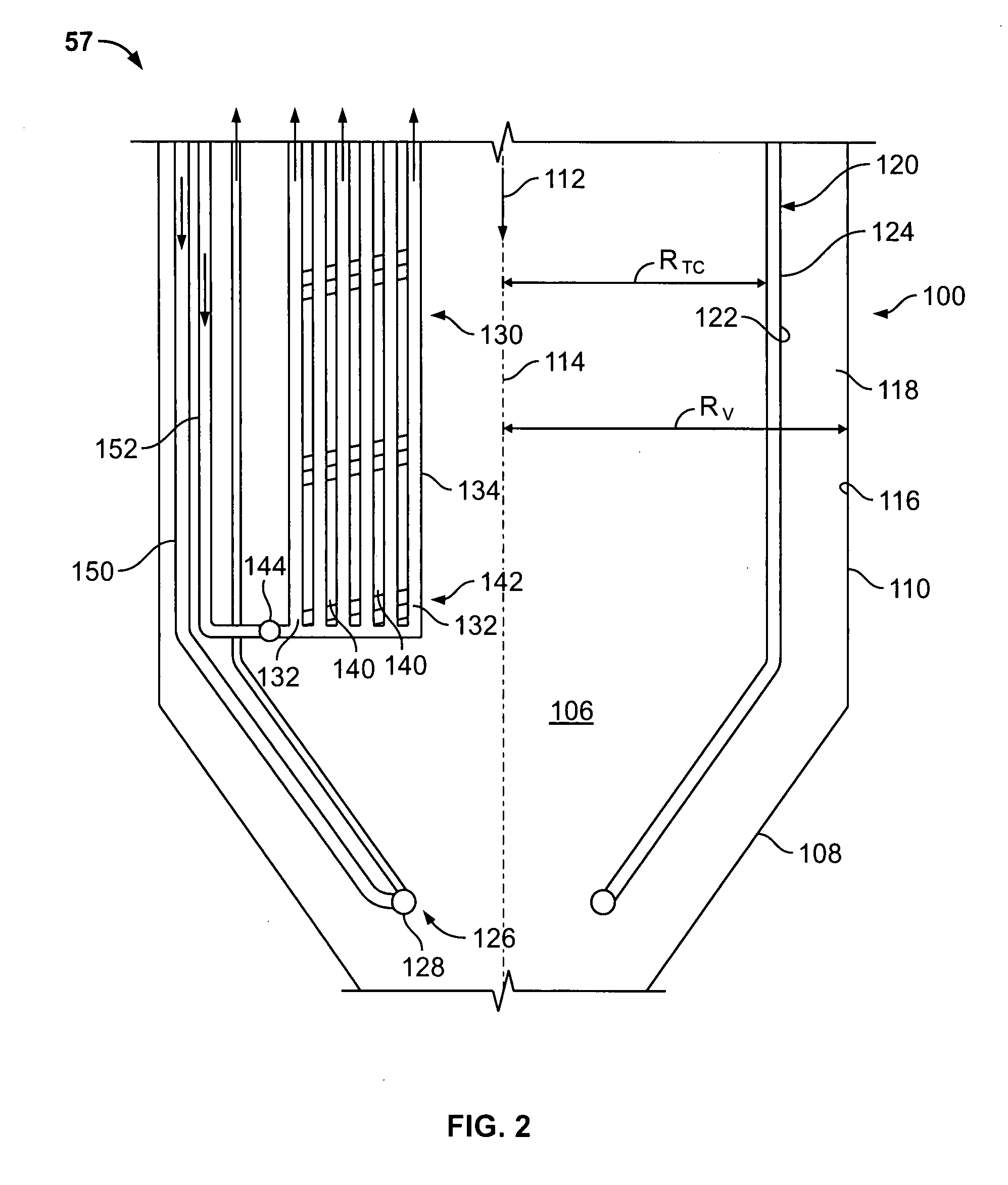
[0020]The present invention generally provides exemplary syngas coolers to facilitate cooling syngas in an integrated gasification combined-cycle (IGCC) power generation system. The embodiments described herein are not limiting, but rather are exemplary only. It should be understood that the present invention may apply to any gasification system that includes a radiant cooler.

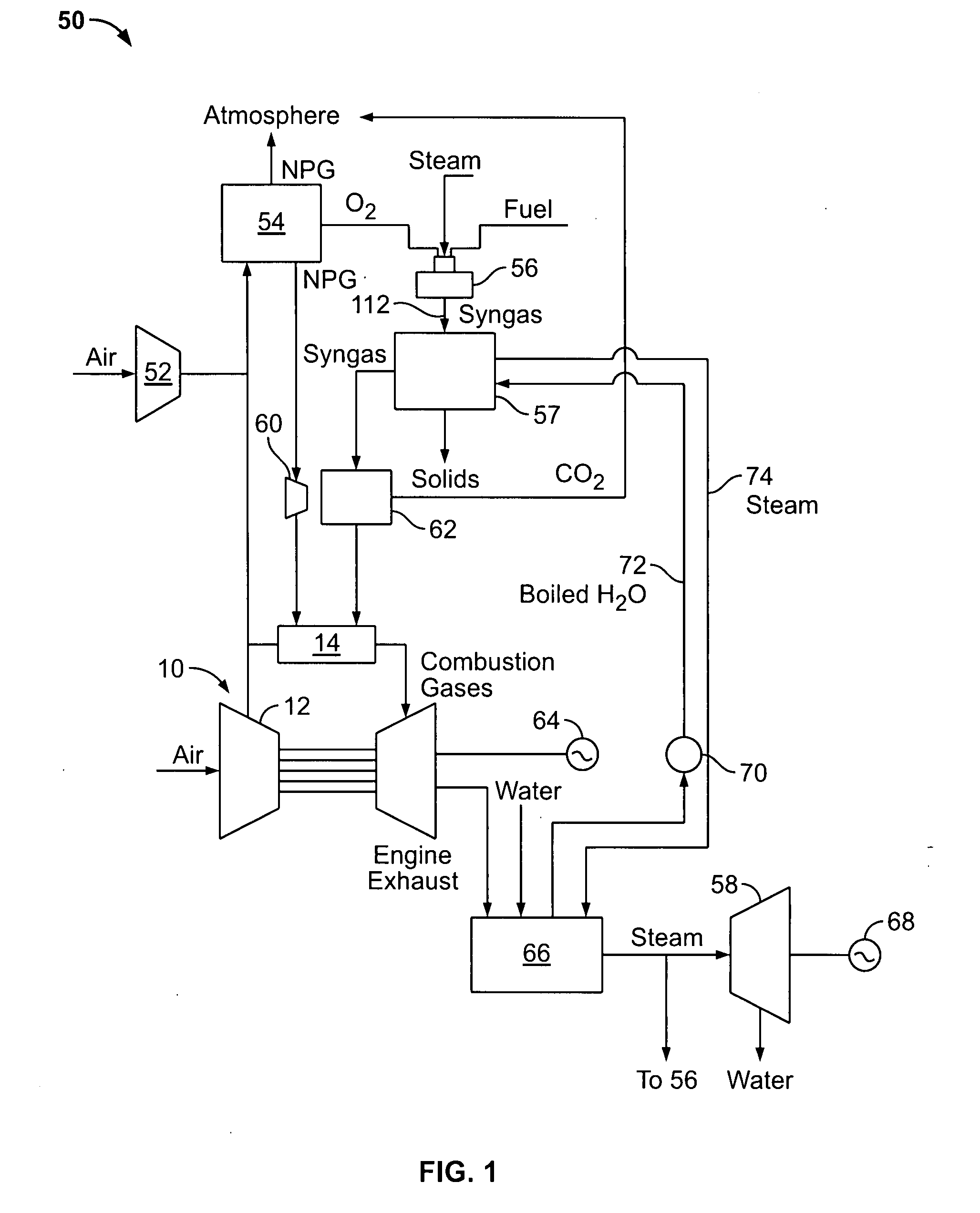
[0021]FIG. 1 is a schematic diagram of an exemplary IGCC power generation system 50. IGCC system 50 generally includes a main air compressor 52, an air separation unit 54 coupled in flow communication to compressor 52, a gasifier 56 coupled in flow communication to air separation unit 54, a syngas cooler 57 coupled in flow communication to gasifier 56, a gas turbine engine 10 coupled in flow communication to syngas cooler 57, and a steam turbine 58.

[0022]In operation, compressor 52 compresses ambient air that is channeled to air separation unit 54. In some embodiments, in addition to compressor 52 or alternativ...


PUM

PropertyMeasurementUnit
angle θUaaaaaaaaaa
angle θUaaaaaaaaaa
angle θDaaaaaaaaaa

Abstract

A method of assembling a radiant cooler is provided. The method includes providing a vessel shell that includes a gas flow passage defined therein that extends generally axially through the vessel shell, coupling a plurality of cooling tubes and a plurality of downcomers together to form a tube cage wherein at least one of the plurality of cooling tubes is positioned circumferentially between a pair of circumferentially-adjacent spaced-apart downcomers, and orienting the tube cage within the vessel shell such that the tube cage is in flow communication with the flow passage.

Description

CROSS REFERENCE TO RELATED APPLICATIONS[0001]This application is a continuation-in-part of U.S. patent application Ser. No. 11 / 835,158 filed Aug. 7, 2007, which is assigned to the same assignee of the present invention, and is hereby incorporated by reference.BACKGROUND OF THE INVENTION[0002]This invention relates generally to gasification systems, and more specifically to a radiant cooler.[0003]At least some known gasification systems are integrated with at least one power-producing turbine system. For example, at least some known gasifiers convert a mixture of fuel, air or oxygen, steam, and / or limestone into an output of partially combusted gas, sometimes referred to as “syngas.” The hot syngas may be supplied to a combustor of a gas turbine engine, which powers a generator that supplies electrical power to a power grid. Exhaust from at least some known gas turbine engines is supplied to a heat recovery steam generator that generates steam for driving a steam turbine. Power gener...

Claims


Application Information

Patent Timeline
Patent Type & Authority Applications(United States)
IPC IPC(8): F28D7/16B01J7/00B23D53/06
CPCF22B1/1846Y10T29/4935F22B21/06
Inventor STOREY, JAMES MICHAELAVAGLIANO, AARON JOHNGERBODE, ASHLEY NICOLELOPEZ, FULTON JOSEBRANNON CORRY, JUDETH HELEN
Owner AIR PROD & CHEM INC
Learn More