
Method and Apparatus for Radiance Capture by Multiplexing in the Frequency Domain

a frequency domain and multiplexing technology, applied in the field of frequency domain multiplexing methods and apparatuses, can solve the problems of inconvenient use, inconvenient operation, and inability to capture a large amount of optical information by conventional cameras,

Active Publication Date: 2009-02-12
ADOBE INC
View PDF43 Cites 138 Cited by
  • Summary
  • Abstract
  • Description
  • Claims
  • Application Information

AI Technical Summary

Benefits of technology

The patent describes various ways to create a mask-based radiance camera which can capture images of a scene's brightness through an optical process called multiplexing. One way involves placing a mask in front of the main camera lens, while another method involves adding a mask inside a conventionally sized camera with a film back. These methods use regular masks instead of just one specific pattern. Overall, this technology allows for more precise measurements of brightness in a variety of settings.

Problems solved by technology

The technical problem addressed in this patent text is how to analyze and improve the performance of light-field or radiance cameras, which capture information about the directional distribution of light in addition to traditional 2-D imaging. Frequency domain analysis techniques have previously been limited to mask-based radiance cameras and cannot provide direct insights into the design of these types of cameras.

Method used


Image

  • Method and Apparatus for Radiance Capture by Multiplexing in the Frequency Domain
  • Method and Apparatus for Radiance Capture by Multiplexing in the Frequency Domain
  • Method and Apparatus for Radiance Capture by Multiplexing in the Frequency Domain

Examples


Embodiment Construction

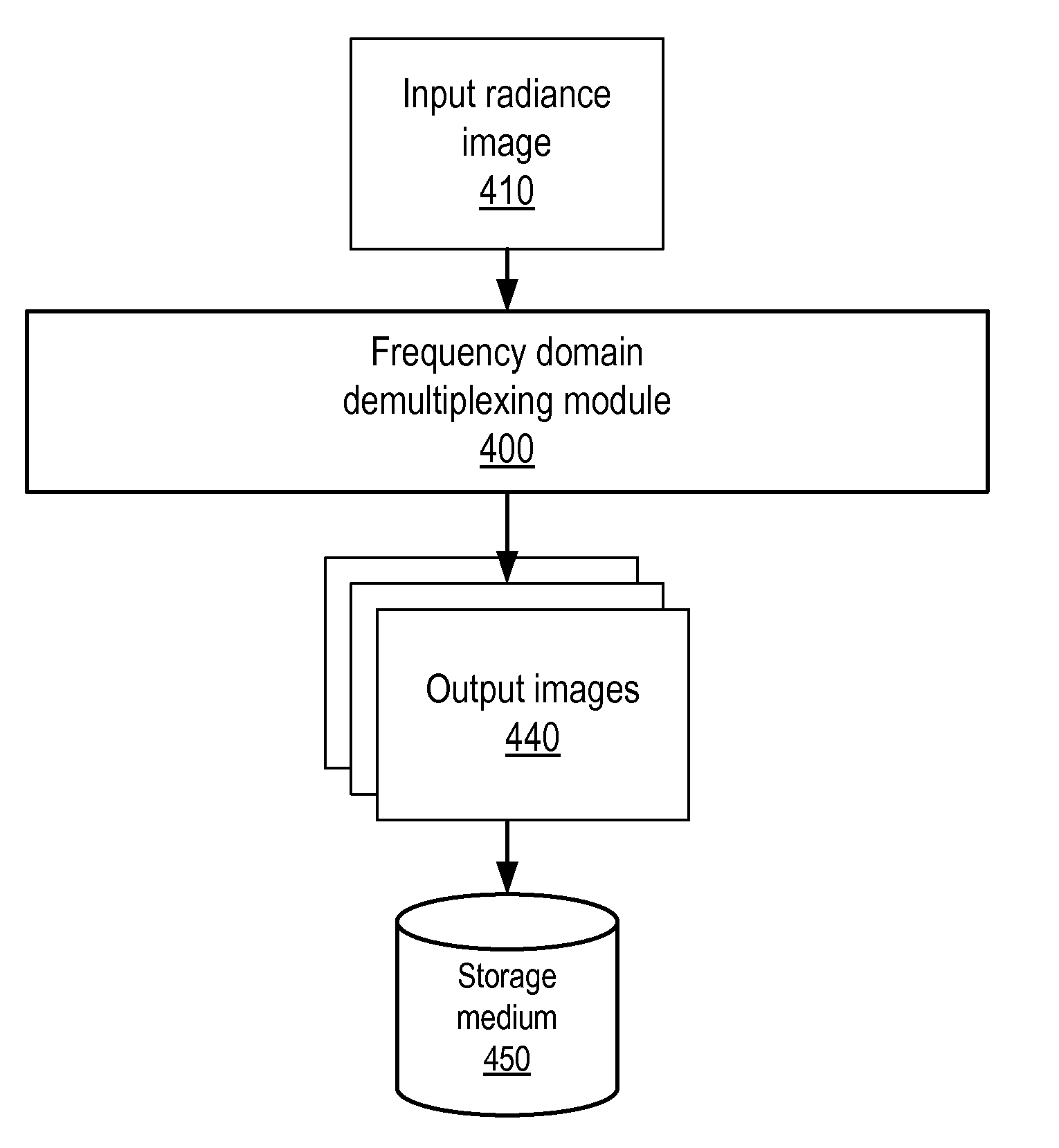
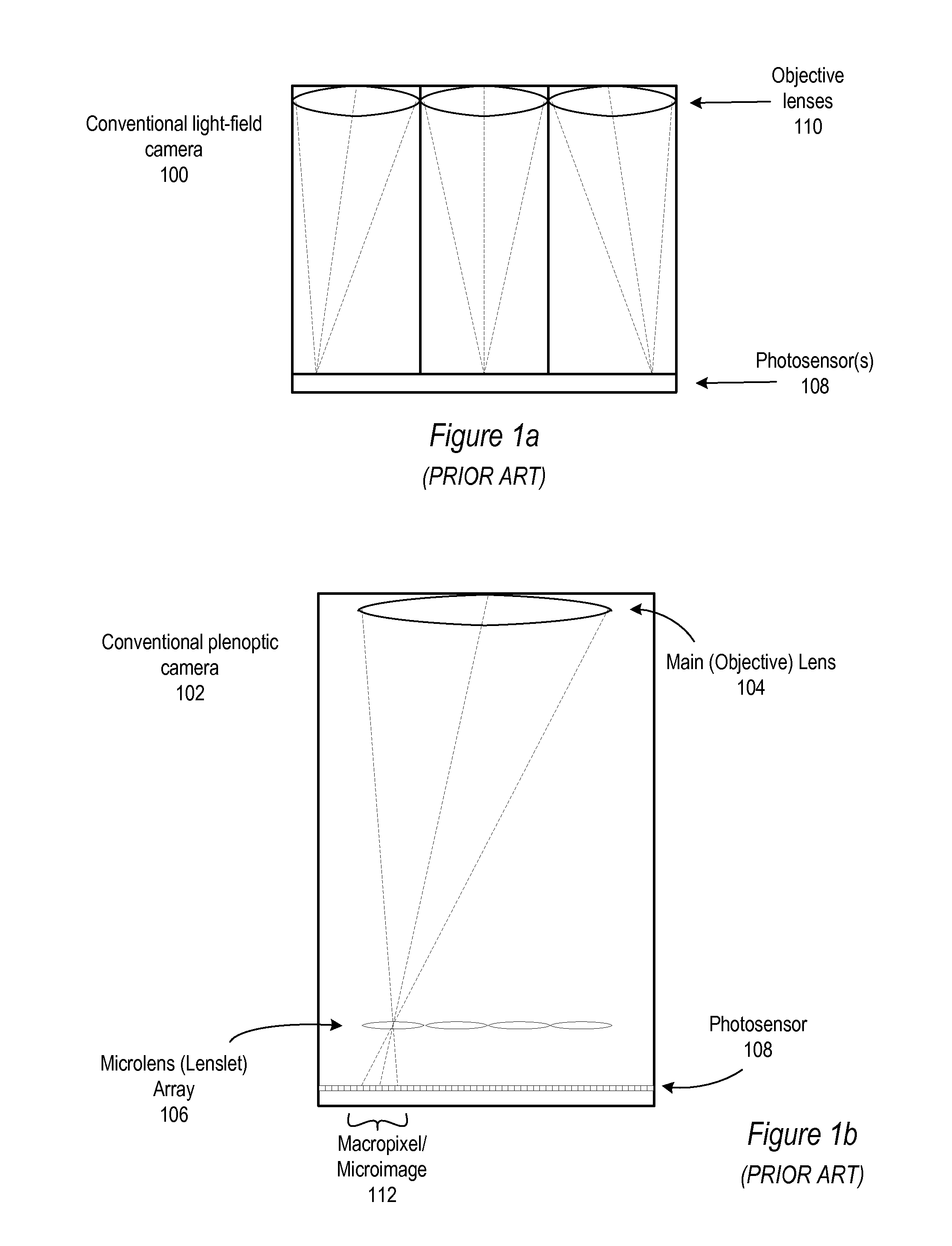
[0055]Various embodiments of a method and apparatus for capturing radiance in the frequency domain, and demultiplexing the captured radiance in the frequency domain, are described. Various embodiments of light-field, or radiance, cameras, including both mask-based and lens-based radiance cameras, are described that multiplex the radiance in the frequency domain by optically mixing different spatial and angular frequency components and capturing the signal via a photosensor (e.g., conventional film or an electronic sensor such as a charge-coupled device (CCD)). Some embodiments of the radiance camera may be based on arrays of “active” optical elements, such as lenses and prisms. Other embodiments of the radiance camera may be based on “passive” optical elements, or masks, such as meshes or grids of circles or pinholes. Both types of radiance cameras may be understood and described according to a mathematical formalism in the frequency domain.

[0056]In the following sections, a mathema...


PUM


Abstract

An external mask-based radiance camera may be based on an external, non-refractive mask located in front of the main camera lens. The mask modulates, but does not refract, light. The camera multiplexes radiance in the frequency domain by optically mixing different spatial and angular frequency components of light. The mask may, for example, be a mesh of opaque linear elements, which collectively form a grid, an opaque medium with transparent openings, such as circles, or a pinhole mask. Other types of masks may be used. Light may be modulated by the mask and received at the main lens of a camera. The main lens may be focused on a plane between the mask and the main lens. The received light is refracted by the main lens onto a photosensor of the camera. The photosensor may capture the received light to generate a radiance image of the scene.

Description


Claims


Application Information

Patent Timeline
Owner ADOBE INC
Learn More