
Pilot pattern design for an OFDM system

a technology of pilot pattern design and communication system, which is applied in the direction of orthogonal multiplex, multiplex communication, polarisation/directional diversity, etc., can solve the problems of poor speech and data transmission quality, and achieve the effect of simple and effective channel estimation

Inactive Publication Date: 2009-02-12
REDWOOD TECHNOLOGIES LLC
View PDF13 Cites 15 Cited by
  • Summary
  • Abstract
  • Description
  • Claims
  • Application Information

AI Technical Summary

Benefits of technology

"The present invention is about a transmitting device for a wireless OFDM communication system that allows for simple and effective channel estimation. The device generates data symbols and pilot symbols and transmits them through multiple transmission antennas. The invention proposes a pilot symbol pattern that is different for each transmission antenna, so that the pilot symbol pattern is unique and can be easily distinguished. This helps to improve the accuracy of channel estimation. The invention also suggests a method for generating the pilot symbols in a way that ensures a different pilot symbol pattern for each transmission antenna. Overall, the invention provides a more efficient and effective way to transmit data symbols and pilot symbols in an OFDM transmission system."

Problems solved by technology

In wireless telecommunication, the transmission quality between a transmitting device, such as a base station, and a receiving device, such as a mobile terminal, depends strongly on the respective transmission environment and is often deteriorated by fading effects and the like.
This often leads to poor speech and data transmission quality, particularly if only one single antenna is used on the transmission side and one single antenna is used on the receiving side.

Method used


Image

  • Pilot pattern design for an OFDM system
  • Pilot pattern design for an OFDM system
  • Pilot pattern design for an OFDM system

Examples


Embodiment Construction

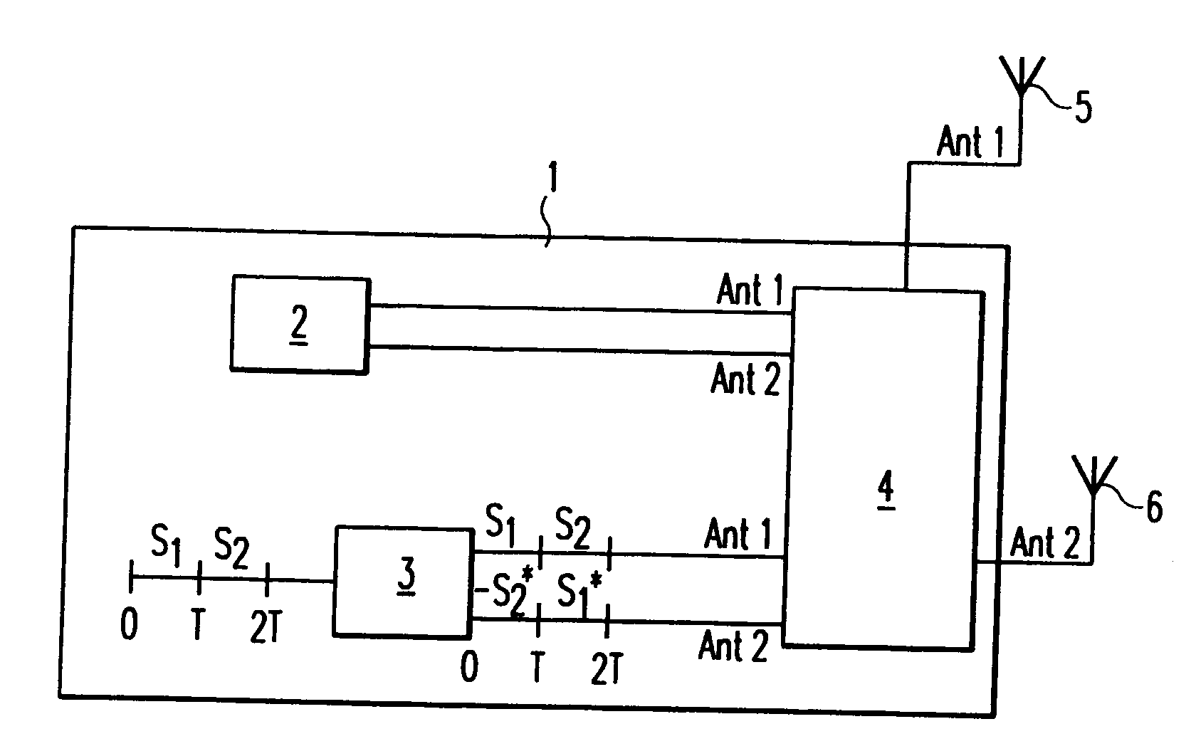
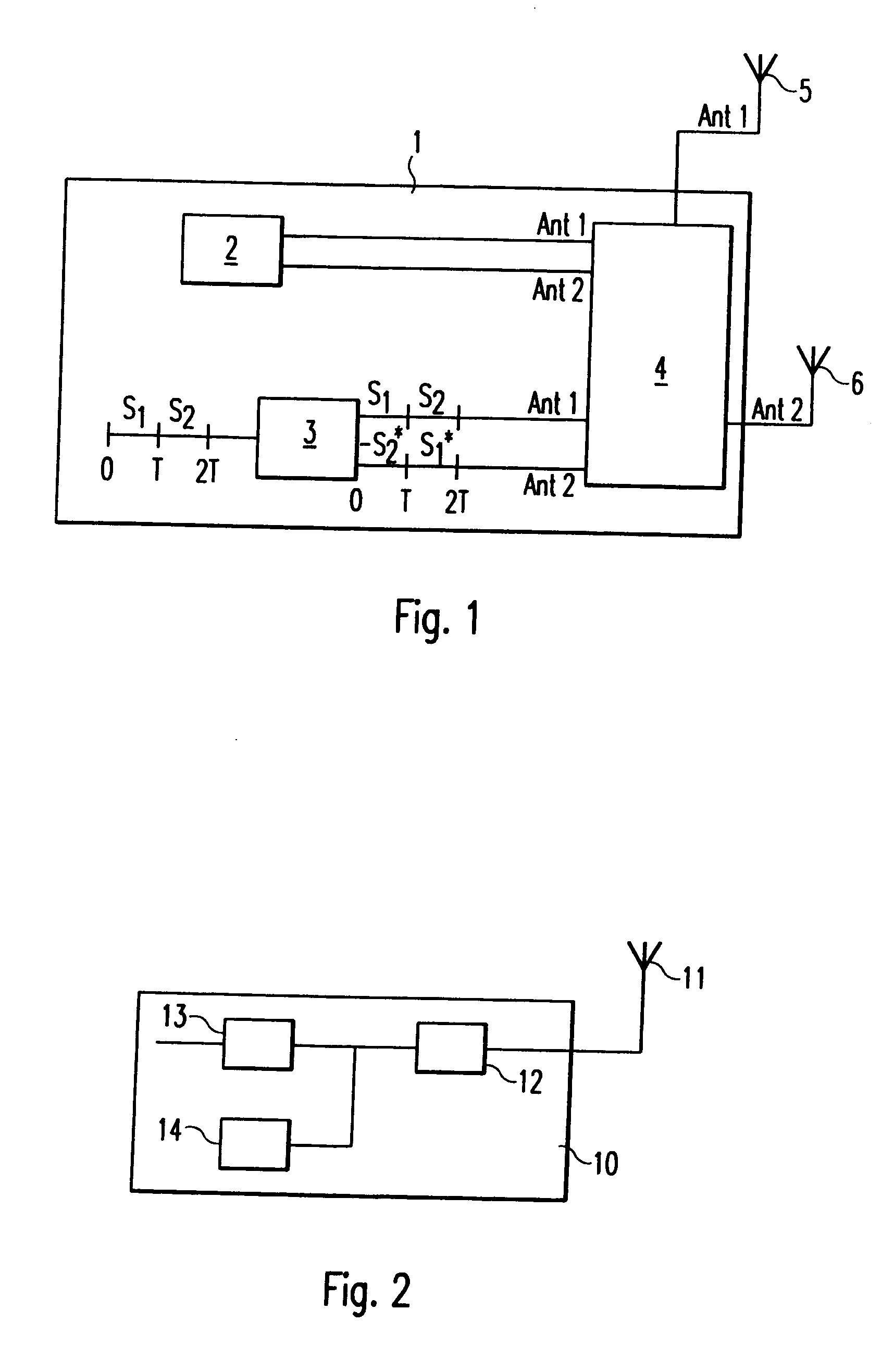
[0039]In FIG. 1, the block diagram of a base station 1 of a wireless orthogonal frequency division multiplex (OFDM) communication system is shown, which comprises a transmitting device according to the present invention. It is to be understood that in FIG. 1 only elements important for the understanding of the present invention are shown. Further elements, such as coding means, modulation means, RF part and the like necessary for the operation of the base station are omitted for the sake of clarity.

[0040]The base station 1 comprises a first antenna 5 and a second antenna 6 being arranged spaced apart from each other, e.g. in a space diversity arrangement. In thus case, the first antenna 5 may also be called a non-diversity antenna and the second antenna 6 can also be called a diversity antenna. The space diversity arrangement of the first antenna 5 and the second antenna 6 is so that the two antennas 5 and 6 are sufficiently separated in space, so that the signals transmitted by the...


PUM


Abstract

The present invention relates to a transmitting device and a receiving device in a wireless orthogonal frequency division multiplex (OFDM) communication system with space time transmit diversity (STTD). Further, the present invention relates to a channel estimation method for performing a channel estimation in such a wireless communication system, in which the transmitting device comprises a first and a second antenna for transmitting signals with space time transmit diversity. The first and the second antenna means are arranged spaced apart from each other in a space diversity arrangement, whereby first and second pilot symbols are transmitted via said first and said second antenna means, respectively. Some of the second pilot symbols are orthogonal to corresponding ones of the first pilot symbols, so that a channel estimation to separately determine the transmission quality of signals transmitted from the first and the second antenna means, respectively, can be performed in a receiving device which receives the signals with only one single antenna.

Description

CROSS-REFERENCE TO RELATED APPLICATIONS[0001]This application is a divisional of U.S. application Ser. No. 11 / 338,645 filed Jan. 25, 2006 which is a divisional of U.S. application Ser. No. 09 / 898,389 filed Jul. 3, 2001, now U.S. Pat. No. 7,221,645 and claims the benefit of priority from the European Patent Application No. 00 114 423.7, filed Jul. 5, 2000, the entire contents of each of which are incorporated herein by reference.BACKGROUND OF THE INVENTION[0002]1. Field of the Invention[0003]The present invention relates to a transmitting device of a wireless orthogonal frequency division multiplex (OFDM) communication system.[0004]2. Description of the Related Art[0005]In wireless telecommunication, the transmission quality between a transmitting device, such as a base station, and a receiving device, such as a mobile terminal, depends strongly on the respective transmission environment and is often deteriorated by fading effects and the like. This often leads to poor speech and dat...

Claims


Application Information

Patent Timeline
Patent Type & Authority Applications(United States)
IPC IPC(8): H04J11/00H04L27/28H04B7/06H04B7/26H04L1/06H04L27/26
CPCH04B7/0669H04L1/0618H04L1/0625H04L1/0668H04L27/2601H04L5/0048H04L25/0226H04L27/2613H04L5/0023H04L27/2626H04L5/0007
Inventor WANG, ZHAOCHENGSTIRLING-GALLACHER, RICHARD
Owner REDWOOD TECHNOLOGIES LLC
Learn More