Apparatus and method for handling special windows in a display

a technology of display and apparatus, applied in the field of apparatus and methods for handling special windows in displays, can solve the problems of increasing the luminance level over the entire display surface, reducing the overall effectiveness of the display, and prone to look rather murky, so as to achieve the effect of effective presentation of visual information

Inactive Publication Date: 2009-02-05
APPLE INC
View PDF55 Cites 3 Cited by
  • Summary
  • Abstract
  • Description
  • Claims
  • Application Information

AI Technical Summary

Benefits of technology

[0014]Key signals are patterns of colored pixel (picture element) pairs. A color coding scheme enables storage of key signal information in a manner that is easily detectable by the window decoder, yet is not visually discernible, given the limited acuity of the human eye. In additive color display systems, primary colors (red, green, blue) can be mixed to produce secondary colors (yellow, cyan, magenta). If a pixel of a primary color is placed next to a pixel of an opposite secondary color (that is, one not including the primary color) of equal luminance, the resulting pixel pair resembles a single pixel that is an achromatic gray in color. This enables the key signal to be plainly displayed in a gray window frame without causing visual distraction. One primary color channel serves as the data signal, and another is used as a complement to produce the achromatic gray color of pixel pairs.
[0015]The key signal color coding scheme preferably uses the remaining primary color channel in the existing video interface as a video clock signal. A separate clock in the window decoder is synchronized to the video clock signal when a key signal is present. The separate but synchronous internal clock is continuously available to the window decoder, and enables the use of a precise but relative (versus absolute) display coordinate system. The location of any pixel in the display can be determined and controlled by the time elapsed since the last horizontal and vertical synchronization pulses in the existing video interface. No second communications channel for transmission of external timing pulses for precise pixel location is required. The window decoder can use key signal information and existing synchronization pulses to control the timing, and thus location, of special processing for desired portions of the display with respect to the upper left corner of the display.
[0017]The present invention therefore handles special windows in a display, enabling more effective presentation of visual information.

Problems solved by technology

Conventional computer displays are designed to present text and graphics, but are not specifically designed to present video information.
Video information presented in conventional computer displays thus appears to have less contrast between bright and dark areas, and tends to look rather murky.
Raising luminance levels is one possible way to enhance the presentation of video information in computer displays, but problems may arise from indiscriminately raising luminance levels over the entire display surface.
For example, text or graphics outside the special window may become blurred, decreasing the overall effectiveness of the display.
Furthermore, continuously raising luminance levels over the entire display surface may unacceptably accelerate the aging of the display tube.
However, this potential solution presents a number of difficulties.
First, such a system would demand significant additional hardware within a computer system; a second serial interface card would have to be managed by the computer system.
Second, the signals generated by such serial interface hardware would have to be precisely calibrated with the horizontal and vertical video synchronization signals going to the display.

Method used


Image

  • Apparatus and method for handling special windows in a display
  • Apparatus and method for handling special windows in a display
  • Apparatus and method for handling special windows in a display

Examples


Embodiment Construction

[0028]The present invention relates to an improvement in displays, including computer displays. The following description is presented to enable one of ordinary skill in the art to make and use the invention and is provided in the context of a patent application and its requirements. Various modifications to the preferred embodiment will be readily apparent to those skilled in the art and the generic principles herein may be applied to other embodiments. Thus, the present invention is not intended to be limited to the embodiment shown but is to be accorded the widest scope consistent with the principles and features described herein.

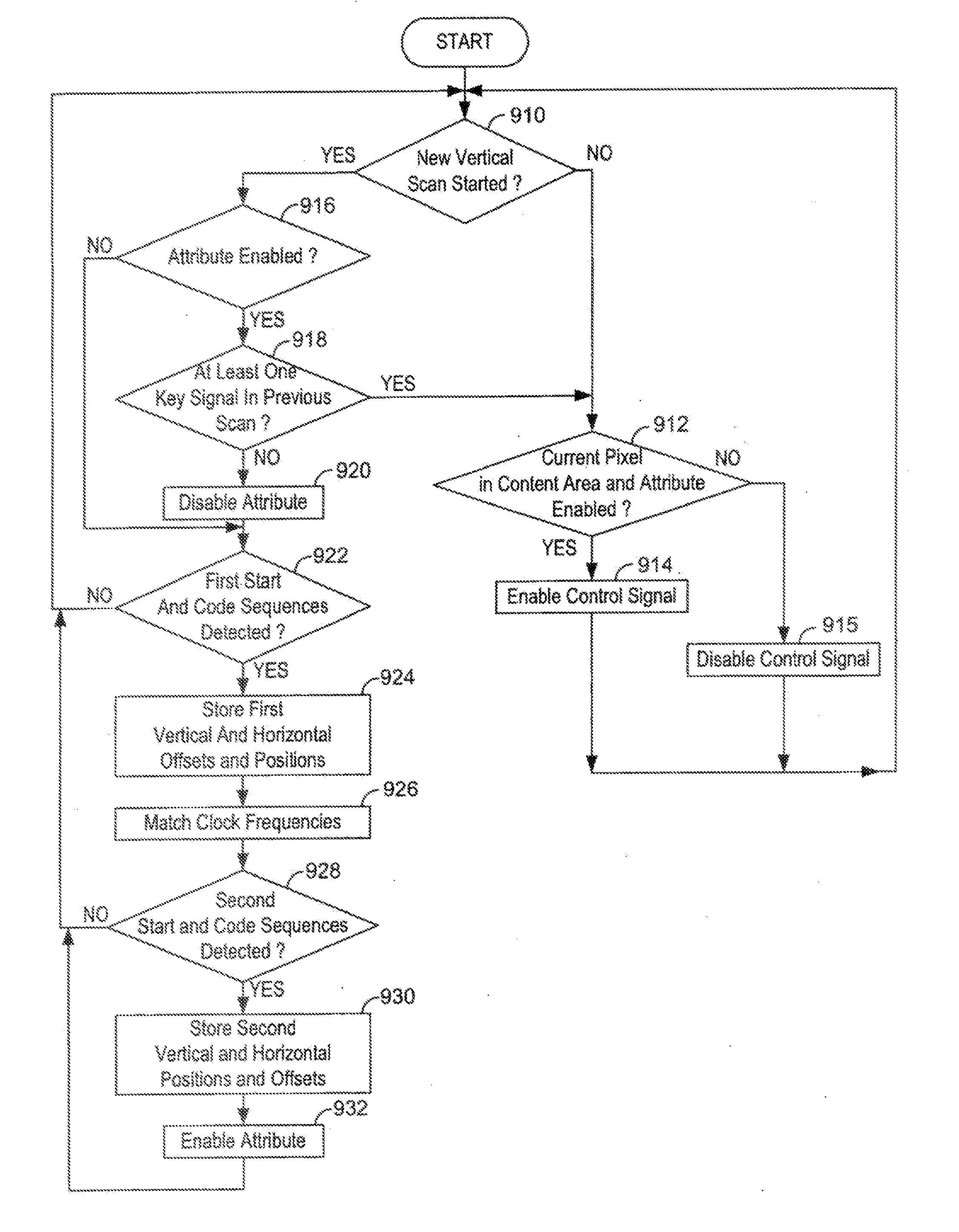
[0029]The present invention comprises an apparatus and method for handling special windows in a display. The invention uses a modified display window frame created by a window manager from an operating system, and transmitted to the display over a video interface. This window frame includes key signals with unique characteristics that are visually unobtr...


PUM


Abstract

An apparatus and method for handling special windows in a display comprises a window manager in an operating system that is called by application programs to create special windows. The window manager embeds static key signals including encoded special window information, such as the coordinates of a window area to be specially processed, into a video RAM. An existing video interface scans the video RAM and transmits display information, including the key signals, to the display. The present invention further comprises a window decoder in the display, that detects the key signals, extracts the encoded special window information, and controls display circuitry performing the desired special processing. The key signal encoding scheme does not create visually discernible display aberrations that could distract the user or interfere with normal window management.

Description

CROSS-REFERENCE TO RELATED APPLICATION[0001]This application is a divisional of U.S. Ser. No. 09 / 160,503, filed Sep. 24, 1998, which is related to co-pending U.S. patent application Ser. No. 08 / 900,964, entitled “System And Method For Generating High-Luminance Windows On A Computer Display Device”, filed on Jul. 25, 1997. The contents of these documents are incorporated herein by reference. These related applications are commonly assigned.BACKGROUND OF THE INVENTION[0002]1. Field of the Invention[0003]This invention relates generally to display devices, and relates more particularly to an apparatus and method for handling special windows in a display.[0004]2. Description of the Background Art[0005]Effective presentation of visual information is an important consideration for manufacturers, designers, and users of displays. Such displays are commonly used for interfacing with computers. Many modern computer operating systems use graphical user interfaces that enclose information from...

Claims


Application Information

Patent Timeline
Patent Type & Authority Applications(United States)
IPC IPC(8): G06F3/048G09G1/16G09G5/10G09G5/14
CPCG09G1/16G09G1/167G09G5/10G09G2370/04G09G2320/02G09G2320/0686G09G5/14
Inventor CAPPELS, SR., RICHARD D.KRAH, CHRISTOPH H.ANDREWS, JOHANNA M.
Owner APPLE INC
Why Eureka
Try Eureka