
Display device, instrument panel, automatic vehicle, and method of driving display device

Active Publication Date: 2009-02-05
SHARP KK
View PDF7 Cites 15 Cited by
  • Summary
  • Abstract
  • Description
  • Claims
  • Application Information

AI Technical Summary

Benefits of technology

[0013]In a preferred embodiment, in accordance with the level of a display signal corresponding to a highest display luminance among display signals having been detected with respect to each of the plurality of regions, the control circuit controls the luminance of each light source block based on a predetermined relationship which assigns a higher luminance for the light source block as a display luminance corresponding to the display signal becomes higher.
[0037]In a preferred embodiment, the step of controlling the luminance of each light source block is performed, in accordance with the level of a display signal corresponding to a highest display luminance among display signals having been detected with respect to each of the plurality of regions, so as to assign a higher luminance for the light source block as a display luminance corresponding to the display signal becomes higher.
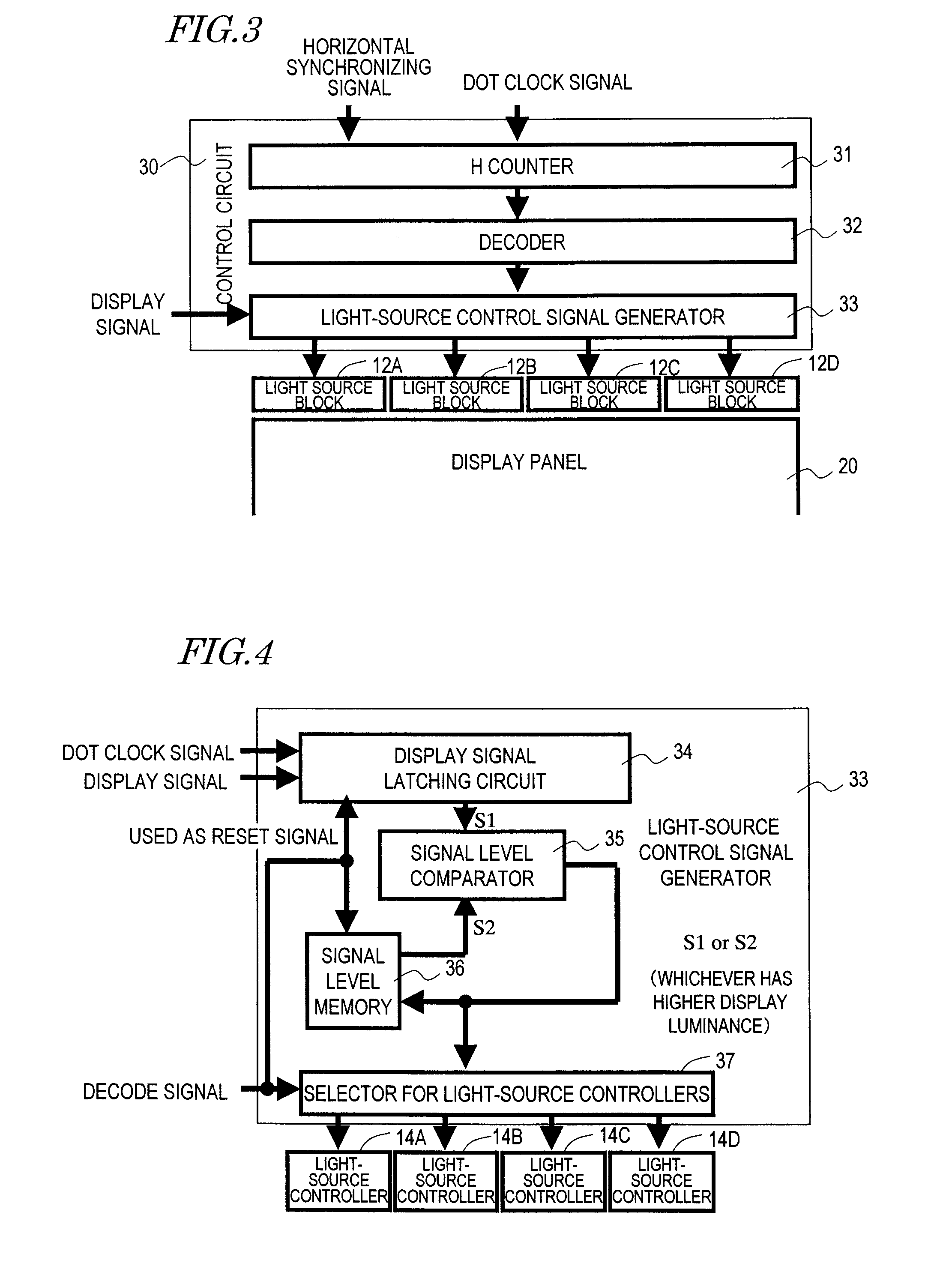
[0040]A liquid crystal display device according to a preferred embodiment of the present invention includes a control circuit for controlling an illuminator. The control circuit detects the level of a display signal (at least one display signal) which is input to each of a plurality of regions within the displaying region of a display panel, and is capable of controlling the luminance of each light source block in accordance with the detected level of the display signal. As a result, the power consumption of the illuminator can be reduced by suppressing unnecessary light emission, and the power consumption of the liquid crystal display device as a whole can also be reduced.

Problems solved by technology

However, LEDs are currently inferior to cold-cathode tubes in terms of efficiency of optical conversion.
Therefore, using an LED to realize a high luminance similar to that of a cold-cathode tube would result in an increased power consumption.
However, depending on the purpose, a liquid crystal display device is required to have a very superbly low power consumption, so that even the technique disclosed in Patent Document 1 may not provide a desired level of low power consumption.

Method used


Image

  • Display device, instrument panel, automatic vehicle, and method of driving display device
  • Display device, instrument panel, automatic vehicle, and method of driving display device
  • Display device, instrument panel, automatic vehicle, and method of driving display device

Examples


Embodiment Construction

[0058]Hereinafter, preferred embodiments of the present invention will be described with reference to the drawings. Note that the present invention is not to be limited to the following preferred embodiments.

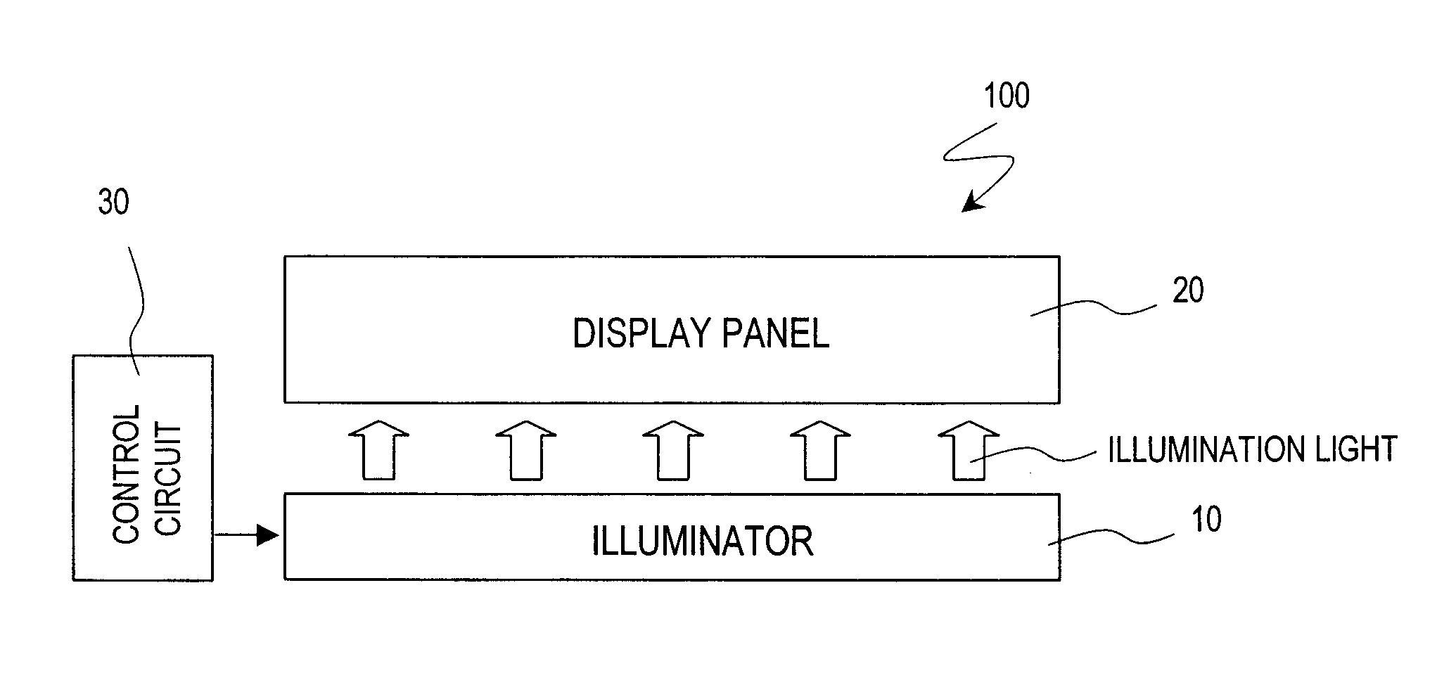
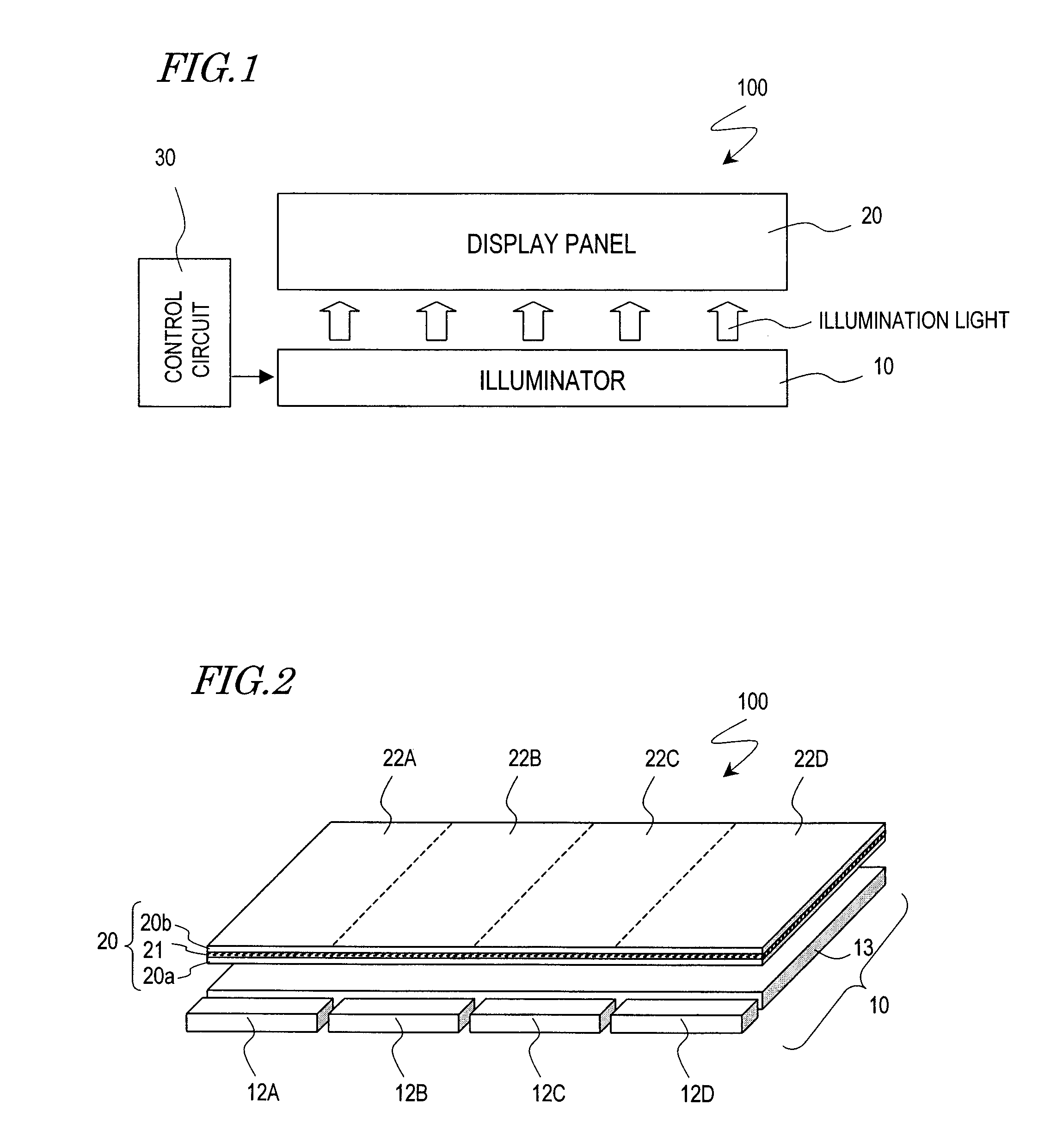
[0059]FIG. 1 and FIG. 2 schematically show a liquid crystal display device 100 according to the present preferred embodiment. As shown in FIG. 1, the liquid crystal display device 100 includes: an illuminator (backlight) 10; a liquid crystal display panel 20 for performing displaying by using light which is emitted from the illuminator 10; and a control circuit 30 which is connected to the illuminator 10 for controlling the illuminator 10.

[0060]As shown in FIG. 2, the illuminator 10 is a backlight of an edge-light type, including: a plurality of light source blocks 12A to 12D; and a light guide plate (optical guide) 13 for guiding the light which is emitted from the light source blocks 12A to 12D to the liquid crystal display panel 20.

[0061]Each of the light source blocks 12A to...


PUM


Abstract

A display device includes an illuminator; a display panel for performing displaying by using light which is emitted from the illuminator; and a control circuit for controlling the illuminator. The illuminator includes a plurality of light source blocks, at least one light source belonging to each of the plurality of light source blocks. A displaying region of the display panel has a plurality of regions each performing displaying by using light which is emitted from a respective one of the light source blocks. The control circuit detects a level of a display signal which is input to each of the plurality of regions, and is capable of controlling a luminance of the respective light source block in accordance with the detected level of the display signal.

Description

BACKGROUND OF THE INVENTION[0001]1. Field of the Invention[0002]The present invention relates to a display device, and in particular to a display device having an illuminator as well as a driving method for the same. The present invention also relates to an instrument panel and an automotive vehicle having such a display device.[0003]2. Description of the Related Art[0004]In recent years, on the strength of being thin and consuming little power, liquid crystal display devices have been broadly used in laptop personal computers, mobile phones, camera-incorporated VTRs having a liquid crystal monitor, etc.[0005]A liquid crystal display device is not a self-light-emitting display device which is capable of emitting light by itself, unlike a CRT (cathode-ray tube) or an EL (electroluminescent) display device. Therefore, a liquid crystal display device includes an illuminator (called a backlight) provided at the rear face side of a liquid crystal display panel, and performs displaying by...

Claims


Application Information

Patent Timeline
IPC IPC(8): G09G3/34
CPCB60K35/00B60K2350/203G09G3/3426G09G2360/16G09G2320/064G09G2360/144G09G2320/0633B60K2360/33
Inventor MIZUMAKI, HIDETAKA
Owner SHARP KK
Learn More