
Tool for driving wedges or slides

a technology for driving wedges and slides, which is applied in the field of tools for installing stator slides, can solve the problems of affecting the operation of stator/rotor bodies, and affecting the operation of operators, so as to reduce the deflection or skew of the push block and reduce the risk. , the effect of reducing the risk

Inactive Publication Date: 2009-02-05
GENERAL ELECTRIC CO
View PDF9 Cites 9 Cited by
  • Summary
  • Abstract
  • Description
  • Claims
  • Application Information

AI Technical Summary

Benefits of technology

[0008]This invention provides a new stator slide driver device that enables a smooth., controlled, non-impacting stator slide assembly technique, with significant reduction or elimination of the aforementioned risks.
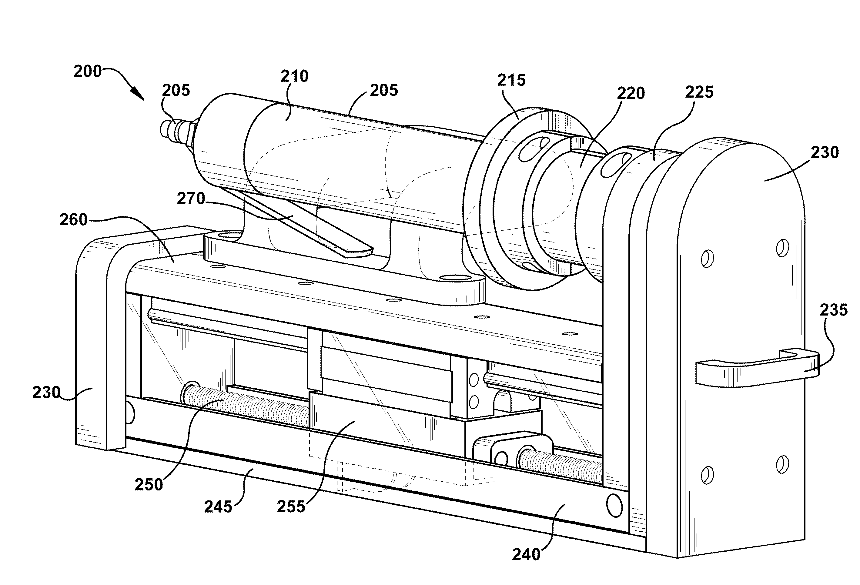
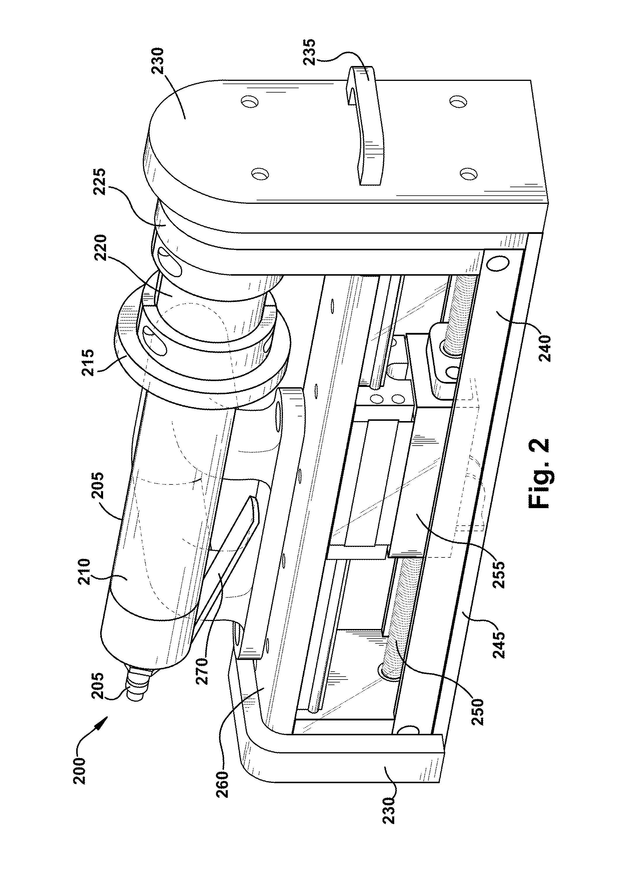
[0009]A tool is provided for driving a slide or wedge within a slot of an armature or field of a dynamoelectric machine. The armature or field includes a core, and the core includes one or more vent slots for facilitating ventilation of the armature or field. The tool includes a drive for applying a driving force, and a push block is connected to the drive. At least one guide rail is configured to cooperate with the push block. The drive operates on the push block to drive a slide or wedge. The at least one guide rail reduces deflection or skew of the push block during a driving operation.

Problems solved by technology

Insulation damage can also be exacerbated by relative movement between the armature windings and stator core.
These methods, however, are time consuming and place considerable strain on the operator.
They also subject the operator to fatigue, the risk of repetitive motion injury and / or hearing damage, and pose a risk to the integrity of the stator core and armature windings.
The hammering technique can also cause snapped stator slides, which result from off-center hits, or an operator can inadvertently miss the slide and hit the stator core, resulting in damage to the core and a lengthy and time-consuming process to fix the damaged core portions.
The uniformity and consistency of the stator wedge and stator slide tightness is also poor using the above-described methods.

Method used


Image

  • Tool for driving wedges or slides
  • Tool for driving wedges or slides
  • Tool for driving wedges or slides

Examples


Embodiment Construction

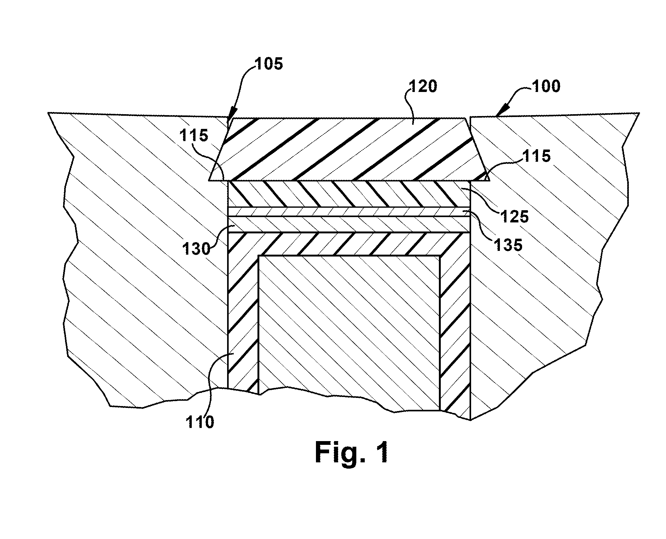
[0021]Referring to FIG. 1, a magnetic stator core for a generator is partially shown at 100. The drawing is not necessarily to scale and the individual elements are shown to illustrate the interaction between the various elements. The stator core can be formed of many laminations of a magnetic steel or iron material. Typically, laminations are arranged in groups, and each group is separated by a spacer (not shown in FIG. 1). The spacers define axially spaced gaps between groups of laminations, and these gaps permit ventilation and cooling of the stator core 100. A plurality of radially oriented stator slots 105 extend axially along the stator core, with armature windings 110 seated therein. Typically, one or two armature windings 110 are present in each slot 105, but three or more could also be present. Each slot 105 is formed adjacent its mouth with a dovetail groove or undercut 115 in opposed side walls of the slot 105, permitting several to many stator wedge 120 and stator slide ...


PUM

PropertyMeasurementUnit
Forceaaaaaaaaaa
Sizeaaaaaaaaaa

Abstract

A tool is provided for driving a slide or wedge within a slot of an armature or field of a dynamoelectric machine. The armature or field includes a core, and the core includes one or more vent slots for facilitating ventilation of the armature or field. The tool includes a drive for applying a driving force, and a push block is connected to the drive. At least one guide rail is configured to cooperate with the push block. The drive operates on the push block to drive a slide or wedge. The at least one guide rail reduces deflection or skew of the push block during a driving operation.

Description

CROSS-REFERENCE TO RELATED APPLICATIONS[0001]This application is a continuation-in-part of application Ser. No. 11 / 881,973, titled “Tool For Driving Wedges Or Slides”, filed on Jul. 31. 2007 and having inventors Brock M. Lape et al.BACKGROUND OF THE INVENTION[0002]This invention relates to dynamoelectric machines and, in particular, to a tool for installing a stator slide under a stator wedge in the stator core of a generator.[0003]Dynamoelectric machines, such as generators, typically employ a stator or armature core comprised of stacked laminations of magnetic material forming a generally annular assembly. An array of axially extending circumferentially spaced stator core slots are formed through the radial inner surface of the annular assembly. Armature or stator windings are disposed in these slots. A rotor or field is coaxially arranged within the stator core and contains field windings typically excited from an external source to produce a magnetic field rotating at the same s...

Claims


Application Information

Patent Timeline
IPC IPC(8): H02K15/02
CPCB25B27/023B25B27/14H02K15/0018Y10T29/5141Y10T29/53143Y10T29/5383Y10T29/53848
Inventor LAPE, BROCK M.BOUSQUET, MICHAEL J.HATLEY, KENNETH J.HATLEY, RICHARD M.NEWMAN, WILLIAM G.TROIANO, KENNETH G.
Owner GENERAL ELECTRIC CO
Learn More