Quiet load for motor testing

Inactive Publication Date: 2009-09-22
THE UNITED STATES OF AMERICA AS REPRESENTED BY THE SECRETARY OF THE NAVY
View PDF28 Cites 9 Cited by
  • Summary
  • Abstract
  • Description
  • Claims
  • Application Information

AI Technical Summary

Benefits of technology

[0006]It is a further object of the present invention to provide such a methodology that is characterized by, or admits of, range versatility regarding speed and torque.
[0008]The present invention is useful in the vibration testing of machines such as motors, particularly those that are designed to be characterized by relative quietness, viz., quiet motors. The present invention's methodology is practicable for acoustic testing or for various other testing purposes. The present invention provides a load without inducing any vibration that is not otherwise present. Featured by the present invention is the novel application of a non-contact, electromagnetic torque load to test electric motors. The inventive device's torque load uniquely describes an “eddy current quiet load” for a motor (e.g., quiet motor), wherein the scientific principle underlying the present invention bears some similarity to the scientific principle underlying a magnetic damper. The non-contact nature of the inventively applied load avoids (or substantially avoids) the introduction of vibration into the test. According to typical inventive practice, the applied torque load is variably controlled.
[0009]Among the advantages afforded by the present invention are the following: smoothness of the applied torque load; quietness of the applied torque load; elimination (or substantial reduction) of introduction of vibration, by the torque load, into the machine being tested; precision of variable control of the torque load; directional independence (e.g., reversibility) of variable control of the torque load. As compared with conventional devices, the inventive device is much smoother with respect to the torque load that can be applied to the motor being tested. The present invention's quiet load generates only steady torques, generating no forces on the test machine rotor, and generating no torques or forces on the test machine frame.

Problems solved by technology

The current methodologies for providing a torque load for vibration testing of machines such as motors are deficient in terms of induced load smoothness, heat generation and vibration generation.
When a quiet motor is to be tested (e.g., for an endurance test), it is unsuitable to use a noisy load for testing, as such would represent an abnormal operating condition for the motor.
A quiet motor is designed to operate quietly, in a quiet environment, and the introduction of a noisy test component would be incongruous.

Method used


Image

  • Quiet load for motor testing
  • Quiet load for motor testing
  • Quiet load for motor testing

Examples


Embodiment Construction

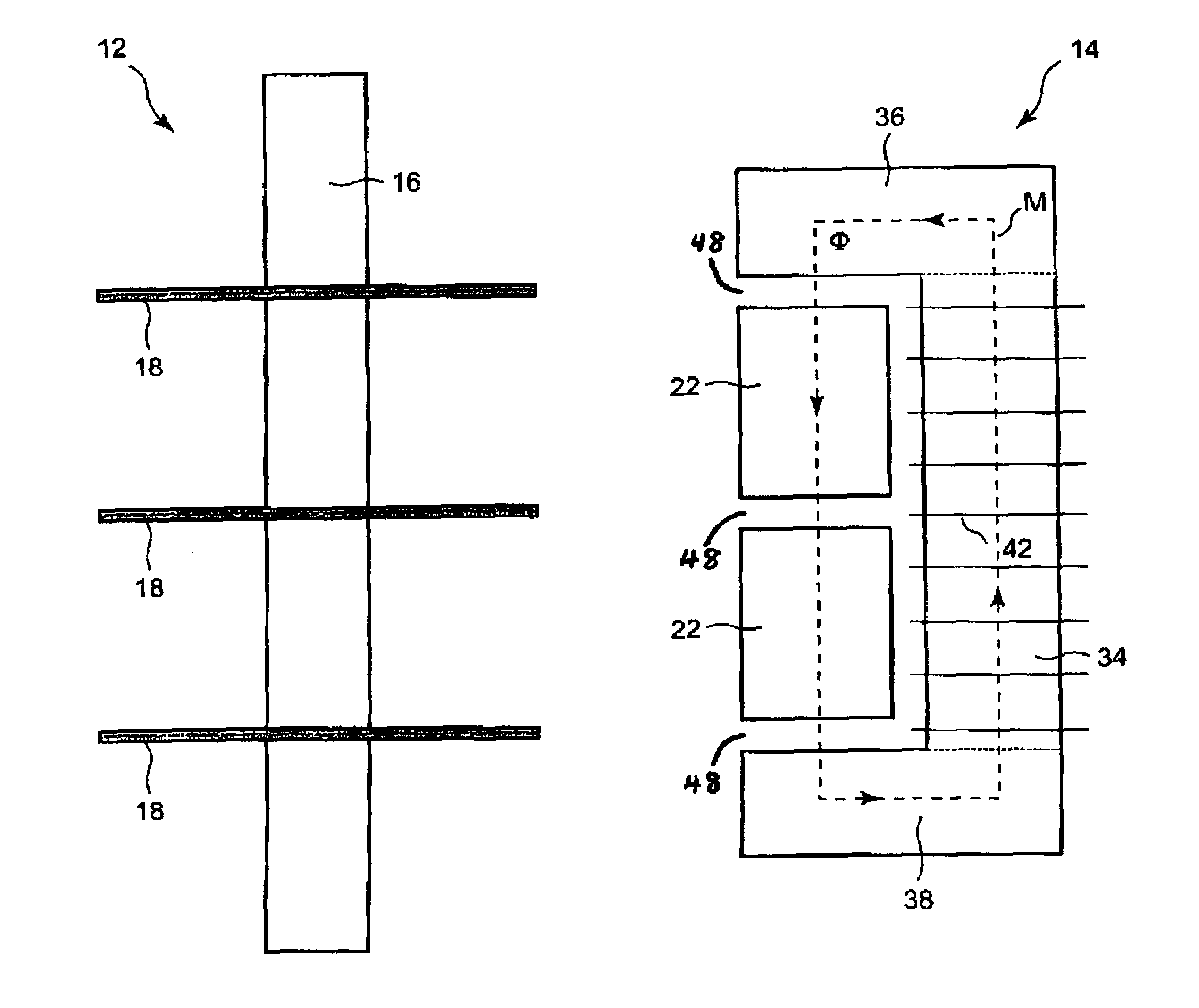
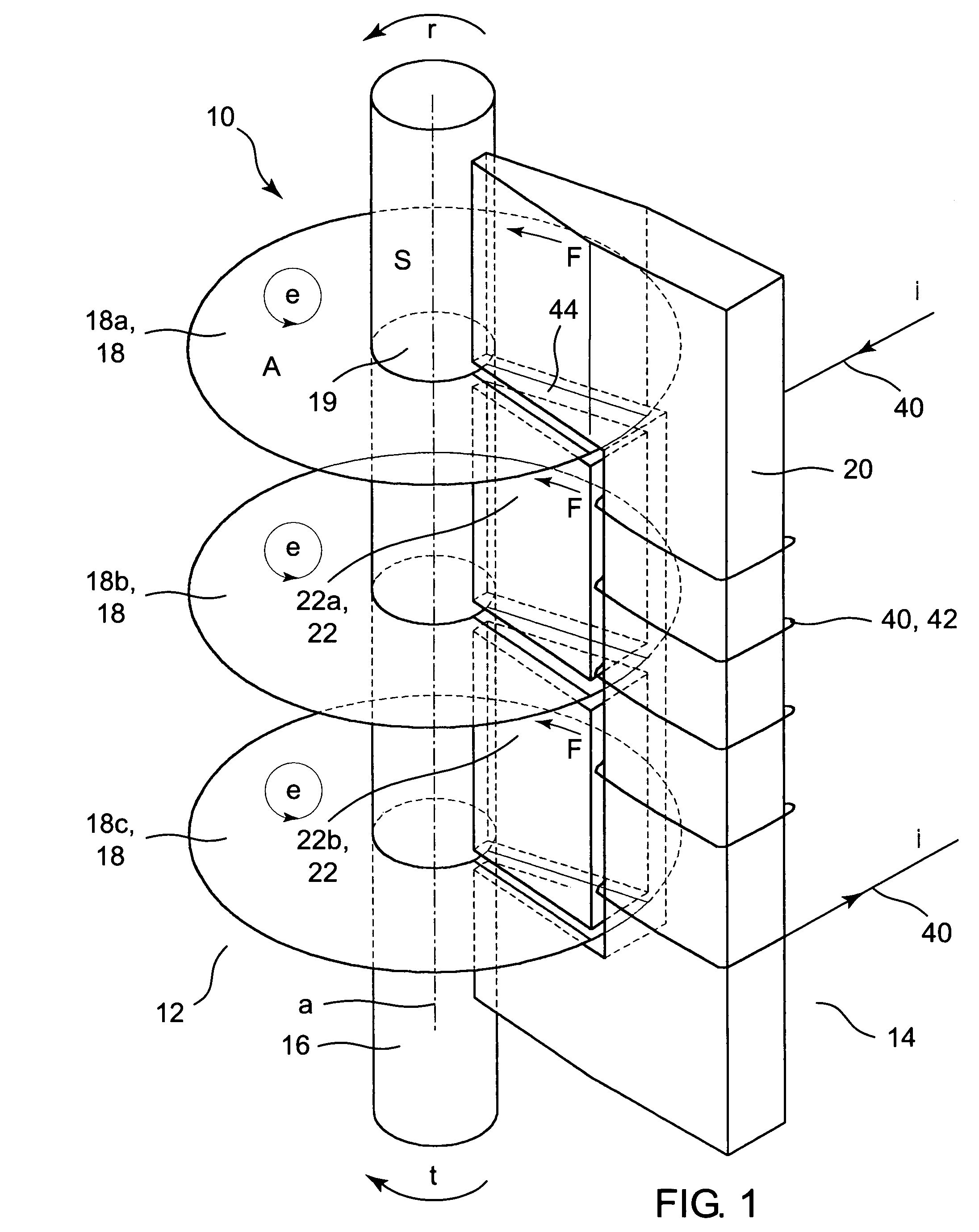
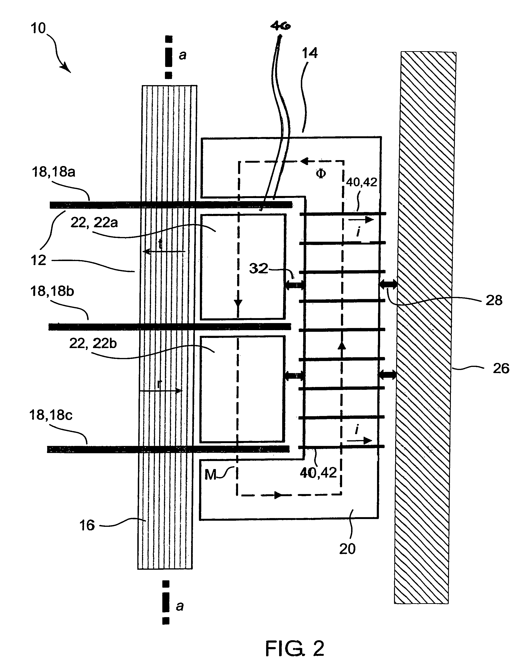
[0023]Referring now to FIG. 1 through FIG. 7, inventive device 10 comprises a rotational unit 12 and at least one stationary unit 14. Rotational unit 12 and stationary unit 14 are separately shown in FIG. 5 and FIG. 6, respectively. Rotational unit 12 includes rotational shaft 16 and at least two electrically conductive disks 18. Each stationary unit 14 includes a bracket-shaped electromagnetic core 20 and at least one wedge-shaped guide block 22. For illustrative purposes, only one stationary unit 14 is shown in FIG. 1 and FIG. 2; however, according to more typical inventive practice, inventive device 10 includes plural (e.g., several or many) stationary units 14, circumferentially arranged such as exemplified in FIG. 3 and FIG. 4.

[0024]Stationary units 14 are shown in FIG. 3 and FIG. 4 to be arranged at approximately ninety degree angles and to be symmetrical with respect to geometric longitudinal rotational axis a of shaft 16. Inventive practice permits utilization of one or prac...


PUM


Abstract

A device for imposing a torque load upon rotating machinery comprises a rotary unit and plural electromagnetic units. The rotary unit includes a shaft and conductive disks discretely fastened thereto. Each electromagnetic unit includes a bracket-shaped magnetic core and one or more ferromagnetic pieces discretely fastened thereto. The device's shaft is joined end-to-end to the motor's shaft, permitting integral axial rotation of the device's shaft, the disks and the motor's shaft. Each electromagnetic unit is placed so that the core “brackets” the two extreme disks, while each piece is between two disks. During rotation, a wire (coiled around each core) conducts current of selected amperage so as to generate a magnetic field of sufficient intensity that a magnetic flux circuit is formed through the stationary core and pieces and the rotating disks, resulting in a Lorentz force associated with the magnetic field and eddy currents engendered in the disks.

Description

STATEMENT OF GOVERNMENT INTEREST[0001]The invention described herein may be manufactured and used by or for the Government of the United States of America for governmental purposes without the payment of any royalties thereon or therefor.BACKGROUND OF THE INVENTION[0002]The present invention relates to machines (e.g., motors) that include rotational members, more particularly to methods and apparatuses for imposing torque loading upon a rotational member for purposes of conducting testing (such as involving vibration, e.g., acoustic vibration) of a machine.[0003]Vibration, such as sound vibration (e.g., that which produces noise), is an important consideration in the operation of various types of machinery. The current methodologies for providing a torque load for vibration testing of machines such as motors are deficient in terms of induced load smoothness, heat generation and vibration generation. The devices conventionally used for motor testing include Prony brakes, water brakes...

Claims


Application Information

Patent Timeline
IPC IPC(8): H02K49/02
CPCH02K49/046
Inventor DOUGHTY, SAMUEL P. S.
Owner THE UNITED STATES OF AMERICA AS REPRESENTED BY THE SECRETARY OF THE NAVY
Why Eureka
Try Eureka