
Vehicle Pedal Controls proof against Misapplication of Accelerator

a technology of accelerator and pedal, which is applied in the direction of brake safety systems, mechanical control devices, foot actuation initiations, etc., can solve the problems of emotional shock of the driver, misapplication of accelerator instead of brake pedal, and the topic of misapplication of accelerator

Inactive Publication Date: 2009-01-29
KARPACHEV BORIS
View PDF10 Cites 21 Cited by
  • Summary
  • Abstract
  • Description
  • Claims
  • Application Information

AI Technical Summary

Benefits of technology

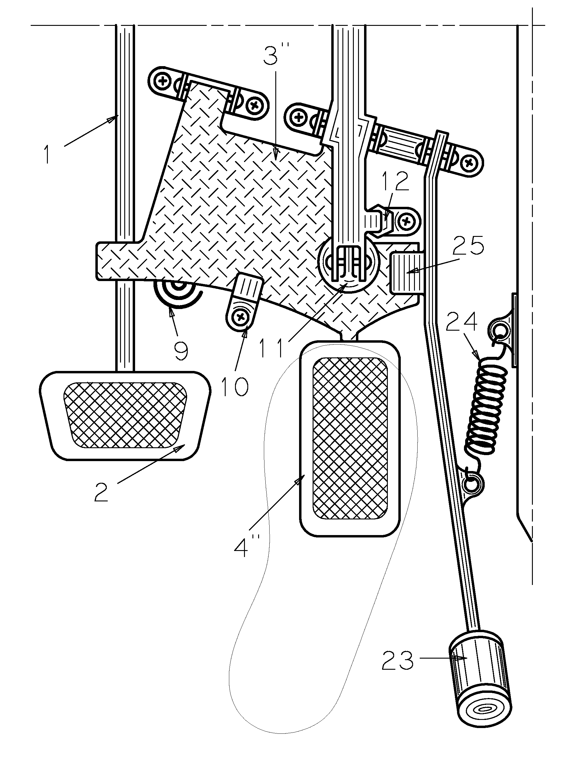
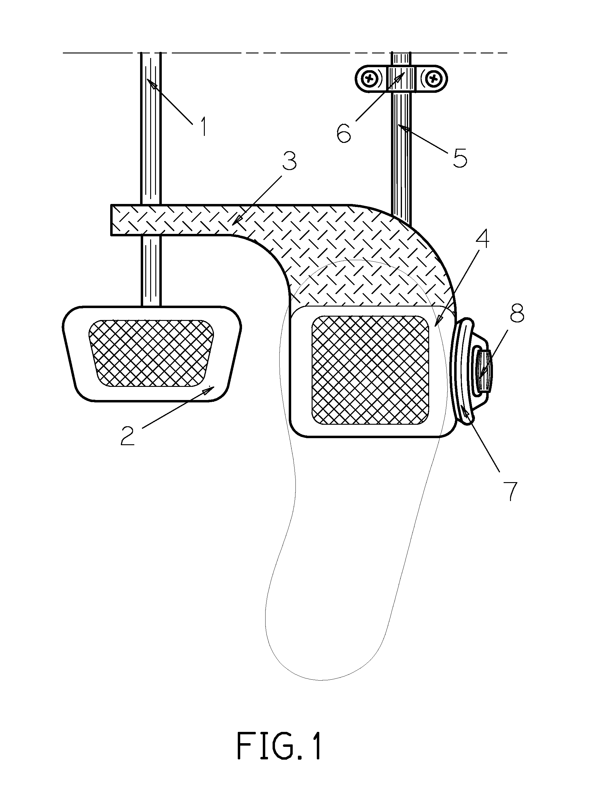
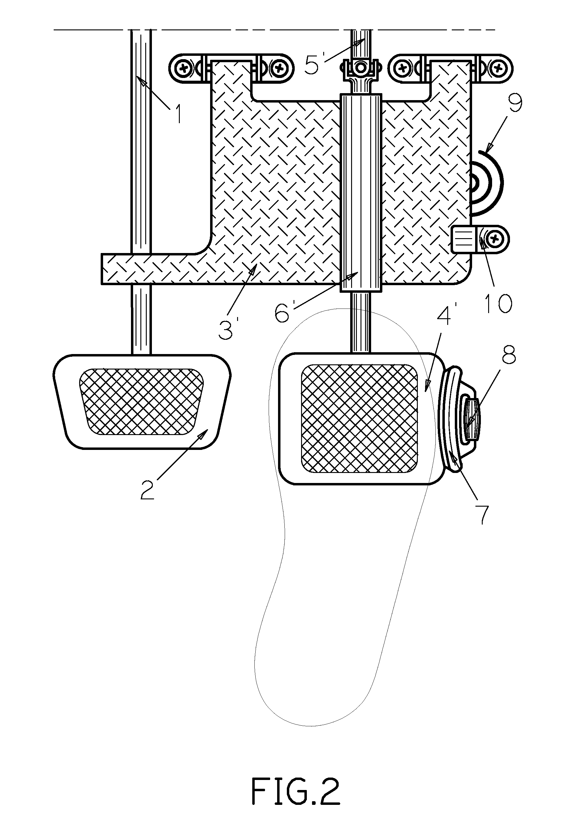
[0018]In some of the embodiments of the invention, an acceleration pedal is made suitable for the inversion-eversion operation by the driver's foot, what provides for better distinction in the driver's muscular feeling of operating the accelerator from that of operating the brake pedal and thus for less probable misapplication of the accelerator pedal instead of the brake one. Also for said better distinction, in other embodiments of the invention, an acceleration pedal is made suitable for the transverse operation. In all embodiments of the invention, with the strong push down of any pedal, either the accelerator or the brake one, the driver engages the brakes of the vehicle—that prevents misapplication of the accelerator.
[0023]If the brake pedal detent is engaged, then it prevents transmitting the driver's operating impact from the first part of the brake pedal to the last part and further to the brakes. If the brake pedal detent is disengaged, then the driver's foot operational impact can be transferred from said first part to the last part of the brake pedal and further to the brakes of the vehicle. Also, the last part of the brake pedal can be operated by the driver's foot directly. The brake pedal detent is disengaged when the driver's foot operational impact is harmful but normal.
[0025]And any above-mentioned detent and / or damping and / or resisting and / or stopping device may be controlled by means of electric current by the vehicle's central processing unit and / or electric controls. A modern vehicle has more than one central processing unit optimizing the engine performance, generally known as engine control unit. Other central processing unit gathers and stores information related to safety and activates safety devices when necessary. Advanced driver assistance systems (containing a central processing unit) are promoting. The immobilizer is becoming the standard feature. So, one of the central processing units of the vehicle can or will be able soon to analyze the situation inside and / or outside the vehicle and / or receive the data on said situation from outside and correspondingly change by means of electric current the capacities of the above-mentioned detents, damping and / or stopping devices for improving the safety. Also, said analysis of safety may be made a person sitting next to the driver, and said person can intervene for improving the safety with mechanical means and / or the electric controls to the above-mentioned detents, damping and / or stopping devices.

Problems solved by technology

Unexpectedness of the acceleration emotionally shocks the driver.
Not every driver, especially elderly one, is able to realize and correct the mistake enough fast.
Such a misapplication of an accelerator instead of a brake pedal is extremely dangerous even deadly often.
Nevertheless, the problem of misapplication of the accelerator continues to be topical, in particular because the number of elderly drivers is increasing.
But, the known vehicle safety devices or systems intended to prevent the misapplication of the accelerator do not provide for sufficient decision of the problem.
It is difficult to add any such a device to already existing vehicle, for example, to those of elderly drivers, therefore they are not widely adopted, and thus, they do not decide the existing problem of the misapplication of the accelerator.

Method used


Image

  • Vehicle Pedal Controls proof against Misapplication of Accelerator
  • Vehicle Pedal Controls proof against Misapplication of Accelerator
  • Vehicle Pedal Controls proof against Misapplication of Accelerator

Examples


Embodiment Construction

[0042]Similar reference characters denote similar elements throughout the several views of the drawings, which illustrate preferred embodiments of the invention. Similar reference characters with primes affixed denote modifications of the similar elements.

[0043]With continue reference to the drawings, any embodiment of a Vehicle Pedal Controls proof against Misapplication of Accelerator comprises a brake pedal rigid body (1) rotating around an axis or fulcrum and the brake pedal platform (2) attached to said body to accommodate a driver's foot, wherein said body and platform are the brake pedal last part, which actuates brakes; a brake pedal first part (3); an acceleration pedal first part (4) with a platform attached to accommodate the driver's foot and an acceleration pedal last part (5), which causes acceleration of the vehicle. Any embodiment of the invention is intended to be mounted inside a vehicle, on the floor in the space for a driver's feet.

[0044]Referring to FIG. 1, the ...


PUM


Abstract

Vehicle Pedal Controls proof against Misapplication of Accelerator allows inversion-eversion operation of the acceleration pedal by the driver's foot for the better driver's distinction of the operation of the acceleration pedal from that of the brake pedal. And any of the invented vehicle control pedals, operable whether downward or transversely or inverse-eversely, provides for the braking of the vehicle with the strong push down of any pedal, whether the accelerator or the brake one,—that prevents the misapplication of the accelerator. In many embodiments of the invention, the pedal comprises the first part being impacted directly by the driver's foot, the last part being connected directly to the appropriate device of the vehicle (brakes or engine) and the detent holding said first part in mechanical relation to said last part, wherein said detent may be disengaged, for example, at misapplication of the acceleration pedal or certain other condition.

Description

CROSS-REFERENCE TO RELATED APPLICATIONS[0001]Not Applicable.STATEMENT REGARDING FEDERALLY SPONSORED RESEARCH OR DEVELOPMENT[0002]Not Applicable.THE NAMES OF THE PARTIES TO JOINT RESEARCH AGREEMENT[0003]Not Applicable.INCORPORATION-BY-REFERENCE OF MATERIAL SUBMITTED ON A COMPACT DISC[0004]Not Applicable.BACKGROUND OF THE INVENTION[0005]1. Field of the Invention[0006]The invention relates generally to the motor vehicles with means for promoting safety of vehicle, its occupants or load, or an external object, and more specifically to the vehicle control pedals proof against driver's misapplication of the vehicle acceleration pedal.[0007]People enjoy the vehicles, which are safe and give predictable response when driven correctly by the operator being in stable mental and physical condition and / or on a safe road and / or in safe situation. But sometimes, the operator intending to slow down or stop the vehicle actually depresses mistakenly the accelerator instead of the brake pedal, or dep...

Claims


Application Information

Patent Timeline
Patent Type & Authority Applications(United States)
IPC IPC(8): G05G1/14G05G1/16G05G5/00
CPCB60T7/06B60T17/18Y10T74/20636Y10T74/20534Y10T74/20906G05G1/48
Inventor KARPACHEV, BORIS
Owner KARPACHEV BORIS
Learn More