
Bone anchor fixture for a medical prosthesis

Active Publication Date: 2009-01-22
COCHLEAR LIMITED
View PDF53 Cites 37 Cited by
  • Summary
  • Abstract
  • Description
  • Claims
  • Application Information

AI Technical Summary

Benefits of technology

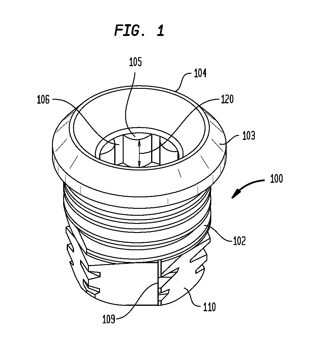
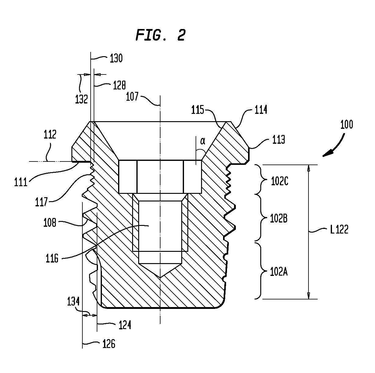
[0009]In one embodiment, an anchoring fixture for anchoring a prosthesis to a skull bone is disclosed. The anchoring fixture comprises a main body configured to be implanted into the skull bone. The main body further comprises a distal tapered apical portion and a first portion adjacent to the distal tapered apical portion. The main body also comprises a second portion adjacent to the first portion. The first portion has a first inner diameter and the second portion has a second inner diameter that is greater than the first inner diameter. This configuration provides compression in the radial direction on the skull bone to improve the initial stability of the anchoring fixture.

Problems solved by technology

In the event that the skin penetrating piece becomes damaged, it may be replaced without removing the anchoring fixture from the skull.

Method used


Image

  • Bone anchor fixture for a medical prosthesis
  • Bone anchor fixture for a medical prosthesis
  • Bone anchor fixture for a medical prosthesis

Examples


Embodiment Construction

[0017]Aspects of the various embodiments disclosed herein are generally directed to providing screw-shaped anchoring fixtures configured to be anchored in the comparatively thin skull bone and having a certain compressive ability in the radial direction to improve the initial stability of the fixture.

[0018]In one embodiment, the anchoring fixture has a main body configured to be inserted in the skull bone and a flange configured to prevent the fixture from completely penetrating through the skull bone. The main body comprises a first and second substantially cylindrical portion. The first portion comprises a screw thread having a first inner diameter and the second portion is adjacent to the flange and has a second inner diameter that is greater than the first inner diameter. Preferably, the second portion has at least one groove extending around the periphery of the cylindrical portion. The groove may have a bottom diameter exceeding the first inner diameter of the screw thread. Pr...


PUM


Abstract

A screw-shaped anchoring fixture for anchoring a prosthesis in the skull bone. The anchoring fixture comprises a main body configured to be implanted into the bone and a flange configured to function as a stop to prevent the main body from completely penetrating through the bone. The main body comprises a distal tapered apical portion, a first portion, and a second portion. The inner diameter of the second portion is greater than the inner diameter of the first portion. The method for inserting the anchoring fixture includes providing the anchoring fixture, drilling a hole, and inserting the anchoring fixture into the hole until the flange contacts the skull bone, wherein the hole has a diameter that is greater than the inner diameter of the first portion and less than the outer diameter of the second portion.

Description

CROSS-REFERENCE TO RELATED APPLICATIONS[0001]This application claims the benefit of U.S. Provisional Application No. 60 / 951,163, entitled “Bone Anchor Fixture for a Medical Prosthesis,” filed Jul. 20, 2007 and U.S. Provisional Application No. 60 / 951,169, entitled “Coupling Apparatus for a Bone Anchored Hearing device,” filed Jul. 20, 2007. These applications are hereby incorporated by reference herein.BACKGROUND[0002]1. Field of the Invention[0003]The present invention relates generally to hearing devices and, more particularly, to anchoring elements for bone anchored hearing devices.[0004]2. Related Art[0005]For persons who cannot benefit from traditional, air conduction hearing aids there are other types of hearing aids on the market commonly referred to as bone anchored hearing aids. Bone anchored hearing aids mechanically transmit sound information to a person's inner ear via the skull bone by means of a vibrator. Such hearing aid devices are typically connected to a percutaneou...

Claims


Application Information

Patent Timeline
IPC IPC(8): A61C8/00
CPCA61C8/0025H04R25/606A61C8/0069A61C8/0066A61B17/8615A61B17/863H04R2460/13
Inventor JINTON, LARSHOLGERSSON, ERIKELMBERG, PETER
Owner COCHLEAR LIMITED
Learn More