
Rotation angle detection device and rotation angle correction method

a detection device and rotation angle technology, applied in the direction of galvano-magnetic devices, instruments, transportation and packaging, etc., can solve the problems of deteriorating detection accuracy of the rotation angle of the axis to be detected, difficult to enhance detection accuracy, and inability to detect an absolute rotation angle, so as to reduce the detection accuracy of the rotation angle. , the effect of less capacity

Inactive Publication Date: 2009-01-22
PANASONIC CORP
View PDF6 Cites 24 Cited by
  • Summary
  • Abstract
  • Description
  • Claims
  • Application Information

AI Technical Summary

Benefits of technology

[0009]The rotation angle detection device of the present invention has a first rotor holding a target connected to an input axis and having an outer circumferential surface to which magnetic poles of alternate polarities are magnetized at an identical interval, and a having a multi-rotatable gear. Furthermore, the rotation angle detection device has a first detector for detecting a rotation angle of the first rotor; a second rotor coupled to the gear of the first rotor, rotated at a lower speed than the first rotor, and having a magnet on the center portion; and a second detector for detecting a rotation angle of the second rotor. The first detection unit detects fine rotation angle, and the second detection unit detects rough absolute rotation angle. From these absolute rotation angles, multiple rotation angle of the first rotor is detected. With such a configuration, it is possible to detect an absolute rotation angle with a high accuracy and a high resolution by using a simple structure and a simple circuit configuration.
[0034]Furthermore, the correction method of the rotation angle of the present invention can correct the reduction of the rotation angle detection accuracy caused by a mechanical error, a magnetic error, an electrical characteristic error, and the like, of a multipole ring magnet or a rotation angle detection unit by using the corrected angle stored in an EEPROM with less capacity. Thus, it is possible to provide a correction method of the rotation angle detection device capable of improving the detection accuracy of rotation angle of the axis to be detected.

Problems solved by technology

Furthermore, since rotation of the code plate and rotation of the axis are carried out via a gear, it is somewhat difficult to enhance the detection accuracy, by backlash and the like.
Furthermore, since this rotation angle detection device can be employed only for detection of the relative rotation angle, it is not suitable for detecting an absolute rotation angle.
Furthermore, in the above-mentioned rotation angle detection device, due to arrangement accuracy and center deflections of gears, detection error in the rotation angle detection unit, or the like, the detection accuracy of the rotation angle of an axis to be detected may be deteriorated.

Method used


Image

  • Rotation angle detection device and rotation angle correction method
  • Rotation angle detection device and rotation angle correction method
  • Rotation angle detection device and rotation angle correction method

Examples


first exemplary embodiment

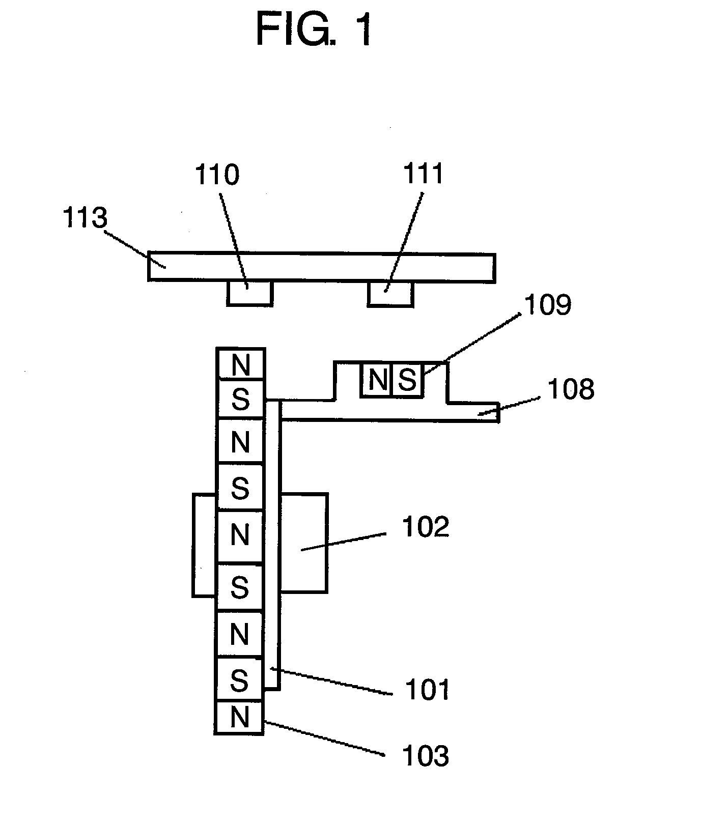
[0124]Hereinafter, the first exemplary embodiment of the present invention is described with reference to FIGS. 1 to 7.

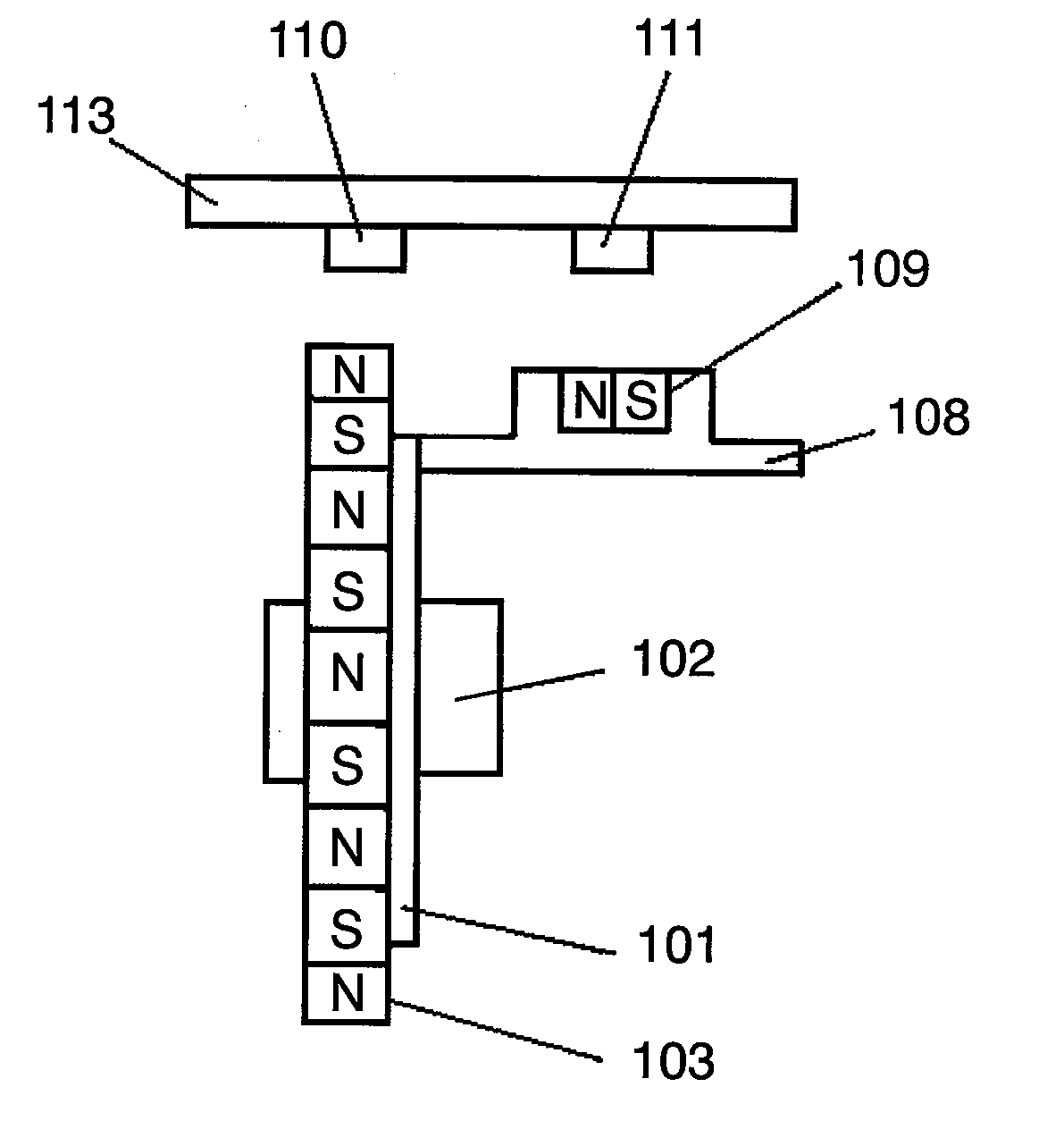
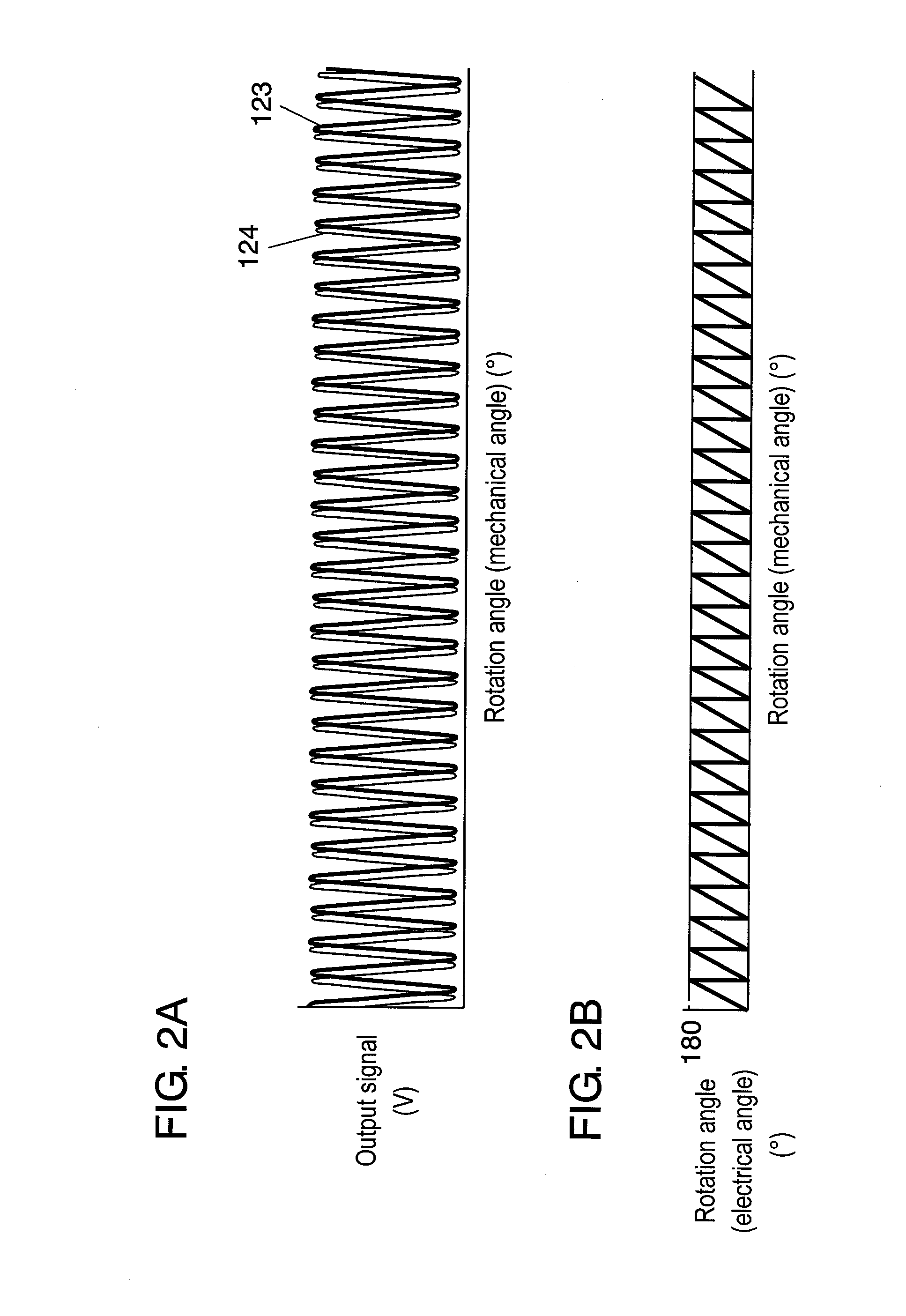
[0125]FIG. 1 is a diagram showing a basic configuration of an absolute rotation angle detection device in accordance with the first exemplary embodiment of the present invention; FIG. 2 is a view showing a rotation angle detection signal of a first magnetic detection element; FIG. 3 is a graph showing a rotation angle detection signal of a second magnetic detection element; and FIG. 4 is a circuit block diagram showing an absolute rotation angle detection device. FIG. 5 is a graph showing an ideal value and an actual value of an absolute rotation angle of the first and second rotors; FIG. 6 is a graph showing a rotation angle operation output signal and an absolute rotation angle in a CPU; and FIG. 7 is a graph showing output signals output from first and second magnetic detection elements.

[0126]In FIG. 1, first rotor 101 is a rotor having a multi-rotatable gear fit...

second exemplary embodiment

[0144]A second exemplary embodiment is described with reference to FIG. 8A to FIG. 14. FIGS. 8A, 8B and 8C show a basic configuration of a rotation angle detection device in accordance with the second exemplary embodiment; FIG. 9 is a circuit block diagram showing a rotation angle detection device; FIGS. 10A and 10B show an output signal from a first detection unit; FIGS. 11A and 11B show an output signal from a third detection unit; FIGS. 12A and 12B show an output signal from a fourth detection unit; FIG. 13 shows rotation angles of third and fourth rotors used for detecting a rotation angle of the first and second rotors; and FIG. 14 is a view to illustrate a method for preventing the occurrence of a detection error of a rotation angle.

[0145]In FIG. 8A to 8B, multi-rotatable first rotor 203 is fitted into input axis 204. First target 205 held by first rotor 203 has an outer circumferential surface to which magnetic poles of alternate polarities are magnetized at an identical inte...

third exemplary embodiment

[0179]Next, a third exemplary embodiment is described with reference to FIGS. 15 to 23. The third exemplary embodiment relates to a highly accurate rotation angle detection device for correcting a mechanical error of a gear or an electrical error in a rotation angle detection unit, and a method for correcting the rotation angle.

[0180]FIG. 15 is a diagram showing a configuration of a rotation angle detection device in accordance with the third exemplary embodiment of the present invention. Multipole ring magnet 302 that is a target is connected to axis to be detected 301 (hereinafter, also referred to as “axis 301”). First rotation angle detection unit 303 is disposed in a position facing multipole ring magnet 302. Worm gear 304 is connected to axis 301. With worm gear 304, wheel gear 305 is engaged. In the center portion of wheel gear 305, magnet 306 is disposed. In a position facing magnet 306, second rotation angle detection unit 307 for detecting a rotation angle is disposed. Mot...


PUM


Abstract

A device for detecting an absolute rotation angle of multiple rotation with a high accuracy and high resolution by using a target connected to the rotation axis and having an outer circumferential surface to which magnetic poles of alternate polarities are magnetized. The device includes: a first rotor holding a target connected to an input axis and having an outer circumferential surface to which magnetic poles of alternate polarities are magnetized at an identical interval and having a multi-rotatable gear; a second rotor connected to the gear of the first rotor, rotated at a low speed by the first rotor, and having a magnet at the center portion; a first detection unit and a second detection unit for detecting the rotation angles of them. With a simple configuration, it is possible to detect an absolution rotation angle with a high accuracy and a high resolution.

Description

[0001]This application is a U.S. National Phase Application of PCT International Application PCT / JP2006 / 302228.TECHNICAL FIELD[0002]The present invention relates to a rotation angle detection device used in a vehicle body control system, and the like. In particular, it relates to a rotation angle detection device for detecting an absolute rotation angle of a multiple rotation steering wheel and a rotation angle correction method.BACKGROUND ART[0003]FIG. 26 shows a conventional rotation angle detection device. Gear 38 is attached via engaged spring 39 to a rotation axis (not shown) whose rotation angle is intended to be detected. Gear 38 is engaged with gear 41 having an outer circumferential end face provided with code plate 40 to which a plurality of magnetic poles are magnetized. Magnetic poles provided on code plate 40 move in accordance with rotation of the rotation axis to be detected. The number of the magnetic poles is counted by detection element 42 provided facing the outer...

Claims


Application Information

Patent Timeline
Patent Type & Authority Applications(United States)
IPC IPC(8): G01B7/30
CPCB62D15/0215B62D15/0245G01D5/2451G01D5/145G01D5/04G01D2205/26
Inventor UEHIRA, KIYOTAKAOIKE, KOUJIICHINOMIYA, NORITAKASASANOUCHI, KIYOTAKASANTO, KOUICHI
Owner PANASONIC CORP
Learn More