
Dynamic spinal stabilization system incorporating a wire rope

Inactive Publication Date: 2009-01-15
VERMILLION TECH
View PDF26 Cites 137 Cited by
  • Summary
  • Abstract
  • Description
  • Claims
  • Application Information

AI Technical Summary

Benefits of technology

[0011]It is a further object of the present invention to provide a surgical implant means for stabilizing two or more non-adjacent vertebrae.
[0012]It is a further object of the present invention to allow loads to be borne by the above mentioned bone graft or bone graft substitute. Bearing these loads has been shown to be beneficial to the healing or consolidation of the graft and incorporation of the graft material with the apposite vertebrae.
[0013]It is a further object of the present invention to allow limited flexion and extensi

Problems solved by technology

Low back pain is one of the most expensive diseases afflicting industrialized societies.
While fusion is effective about seventy percent of the time, there are consequences even to these successful procedures, including a reduced range of motion and an increased load transfer to adjacent levels of

Method used


Image

  • Dynamic spinal stabilization system incorporating a wire rope
  • Dynamic spinal stabilization system incorporating a wire rope
  • Dynamic spinal stabilization system incorporating a wire rope

Examples


Example

DETAILED DESCRIPTION OF THE DRAWINGS

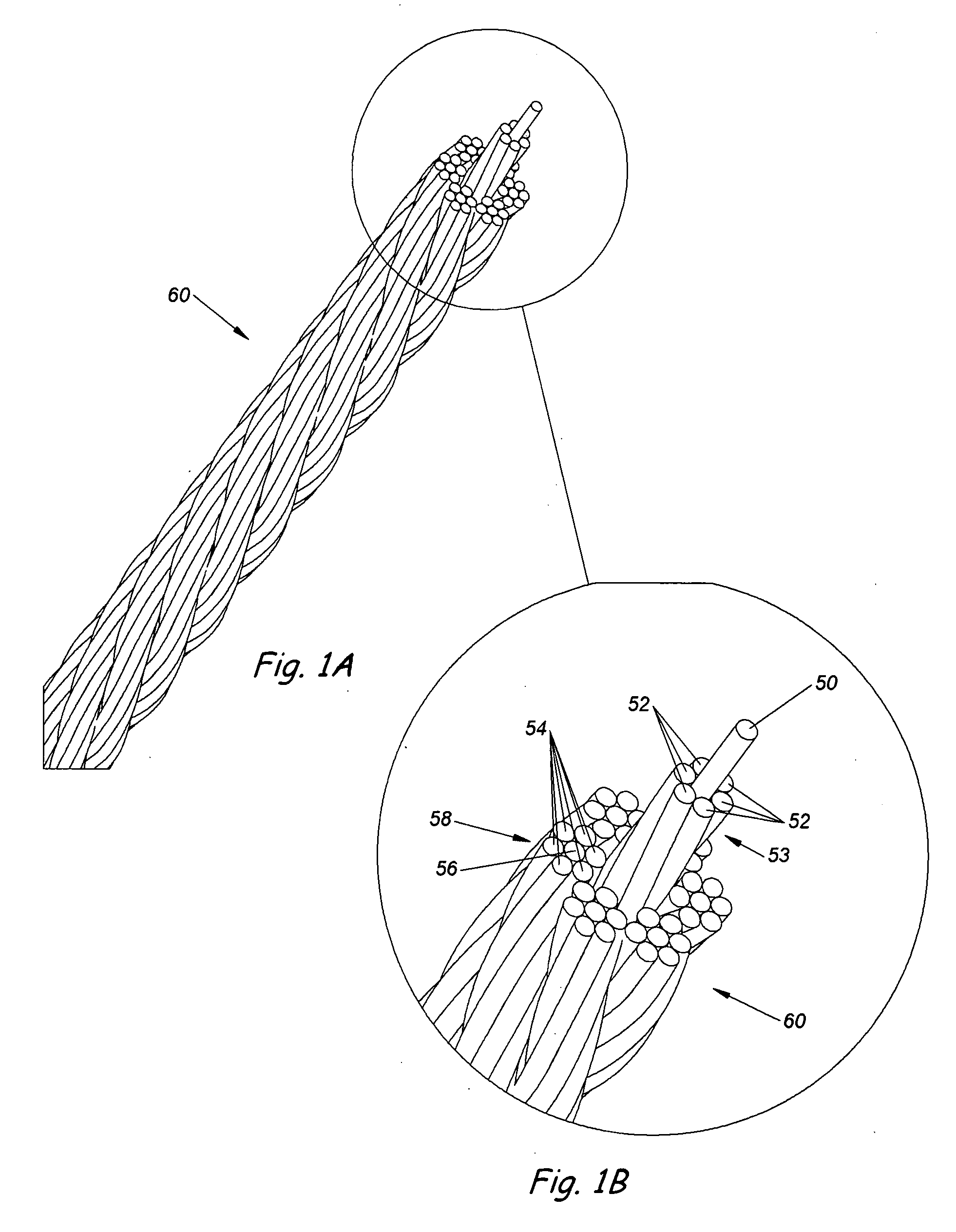
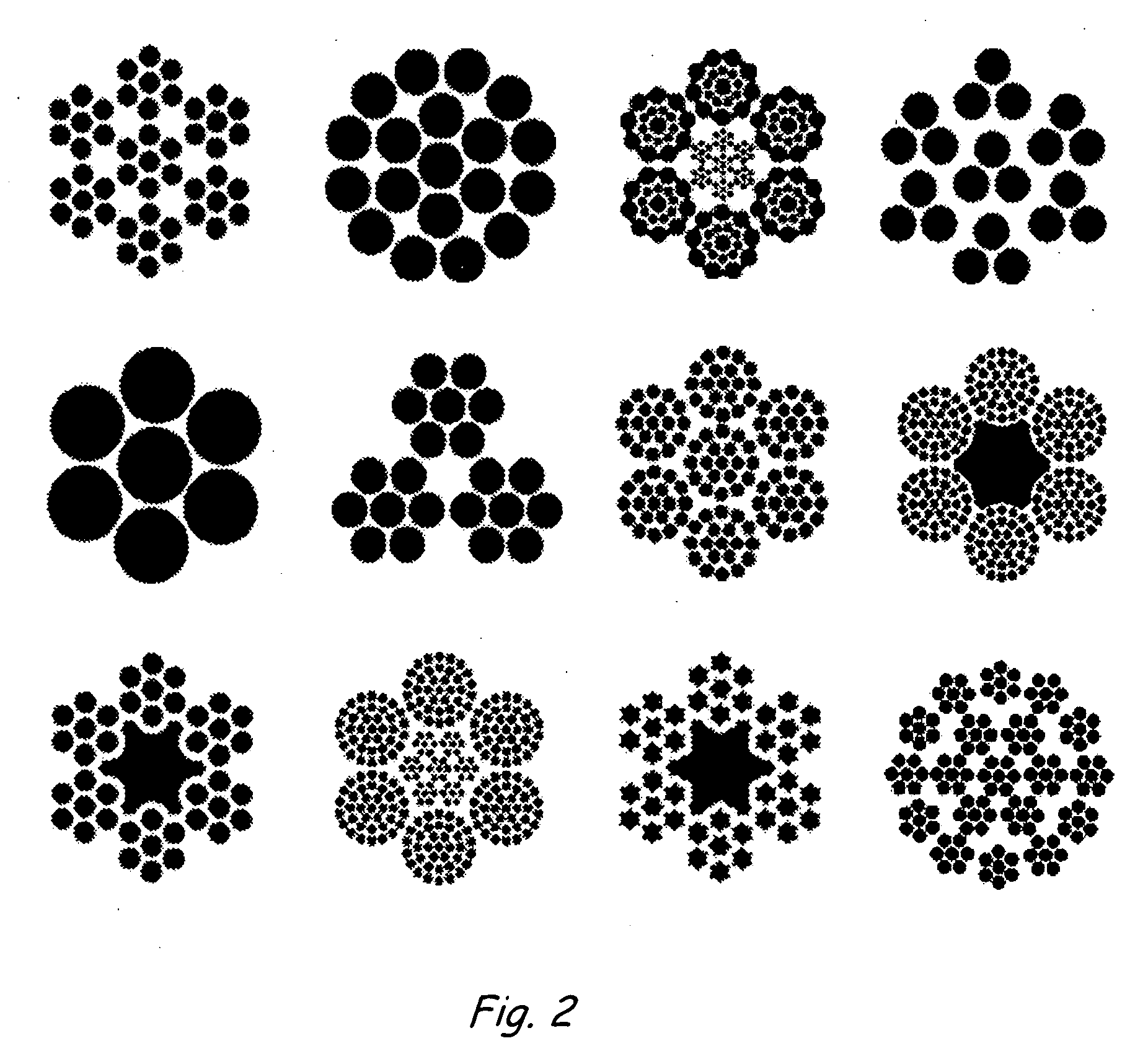
[0037]FIGS. 1A and 1B show a wire rope. Wires 52 are twisted around a core wire 50 in a helical manner to create a first strand 53 of a multi-strand wire rope 60. In the same way, wires 54 are twisted around another core 56 in a helical manner and the resulting strand 58 is twisted around the first strand 53 in a helical manner. Multiple other strands are wrapped around first strand 53 in a helical manner until wire rope 60 is created as shown. This describes just one method of creating a wire rope. In general, the inventors define a wire rope as being made up of a number of strands laid helically about a metallic or non-metallic core; each strand consisting of a number of wires also laid helically about a metallic or non-metallic center. FIG. 2 shows some examples of typical wire rope constructions. This figure is not meant to be an exhaustive list of possible constructions since there are many possible constructions which would serve the purpose...


PUM


Abstract

A device, or series of devices, for use in stabilizing two or more vertebrae of the spine—specifically, a wire rope which is used with pedicle screws as a dynamic spinal stabilization system, thereby allowing limited motion of the vertebrae. The system may also allow load transfer to an intervertebral bone graft or bone graft substitute.

Description

FIELD OF THE INVENTION[0001]The present invention describes a surgical device incorporating a wire rope which is meant to stabilize at least one vertebra relative to another vertebra while transmitting loads and / or motion between the spinal structures.BACKGROUND OF THE INVENTION[0002]Low back pain is one of the most expensive diseases afflicting industrialized societies. With the exception of the common cold, it accounts for more doctor visits than any other ailment. The spectrum of low back pain is wide, ranging from periods of intense disabling pain which resolve, to varying degrees of chronic pain. The conservative treatments available for lower back pain include: cold packs, physical therapy, narcotics, steroids and chiropractic maneuvers. Once a patient has exhausted all conservative therapies, the surgical options range from micro-discectomy, a relatively minor procedure relieving pressure on the nerve root and spinal cord, to fusion which eliminates spinal motion at the level...

Claims


Application Information

Patent Timeline
IPC IPC(8): A61B17/70A61B17/56A61B17/04A61B17/58
CPCA61B17/7005A61B17/705A61B17/7032A61B17/7022
Inventor SONG, JOHN K.GORDON, JEFFREY DAVID
Owner VERMILLION TECH
Learn More