
Catheter for in vivo imaging

a catheter and in vivo imaging technology, applied in the field of catheter, can solve problems such as difficulty in achieving and maintaining a uniform rotational velocity

Active Publication Date: 2009-01-15
VOLCANO CORP
View PDF24 Cites 192 Cited by
  • Summary
  • Abstract
  • Description
  • Claims
  • Application Information

AI Technical Summary

Problems solved by technology

For intravascular imaging, it is difficult to achieve and maintain a uniform rotational velocity due to cables and shafts binding and / or whipping around as it is rotated in the blood vessel.
This is a problem because the angles assumed by the image processor in assembling the image vectors into the cross-sectional image of the body lumens are different from the actual angles at which the image vectors were taken.

Method used


Image

  • Catheter for in vivo imaging
  • Catheter for in vivo imaging
  • Catheter for in vivo imaging

Examples


examples

[0083]The following examples are put forth so as to provide those of ordinary skill in the art with a complete disclosure and description of how the articles, devices, systems, and / or methods claimed herein are made and evaluated, and are intended to be purely exemplary and are not intended to limit the scope of articles, systems, and / or methods. Efforts have been made to ensure accuracy with respect to numbers (e.g., amounts, temperature, etc.), but some errors and deviations should be accounted for.

[0084]OCT images of a NURD mask for the catheter with a vessel in phantom are shown in FIGS. 14, 15, and 16. The examples span the range from mild to moderate NURD with for each case the angular position vs. time and the resulting B-scan profile. The catheter OCT system records 1000 A-lines per rotation. A tube called a resolution mask or NURD mask 650 is placed over the catheter system, as shown in FIG. 13. The NURD mask 650 may include several different sizes to measure the effects of...


PUM


Abstract

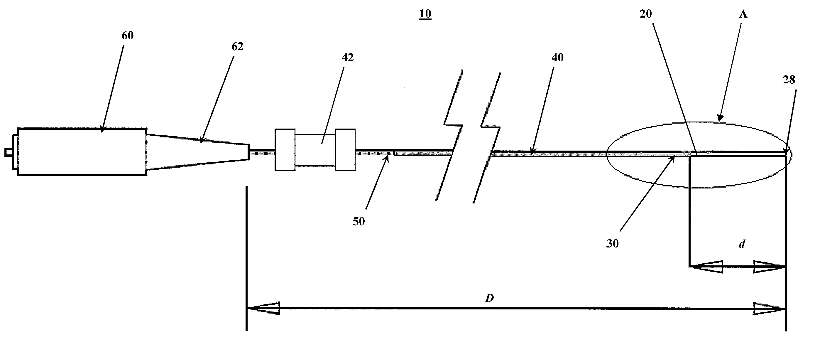
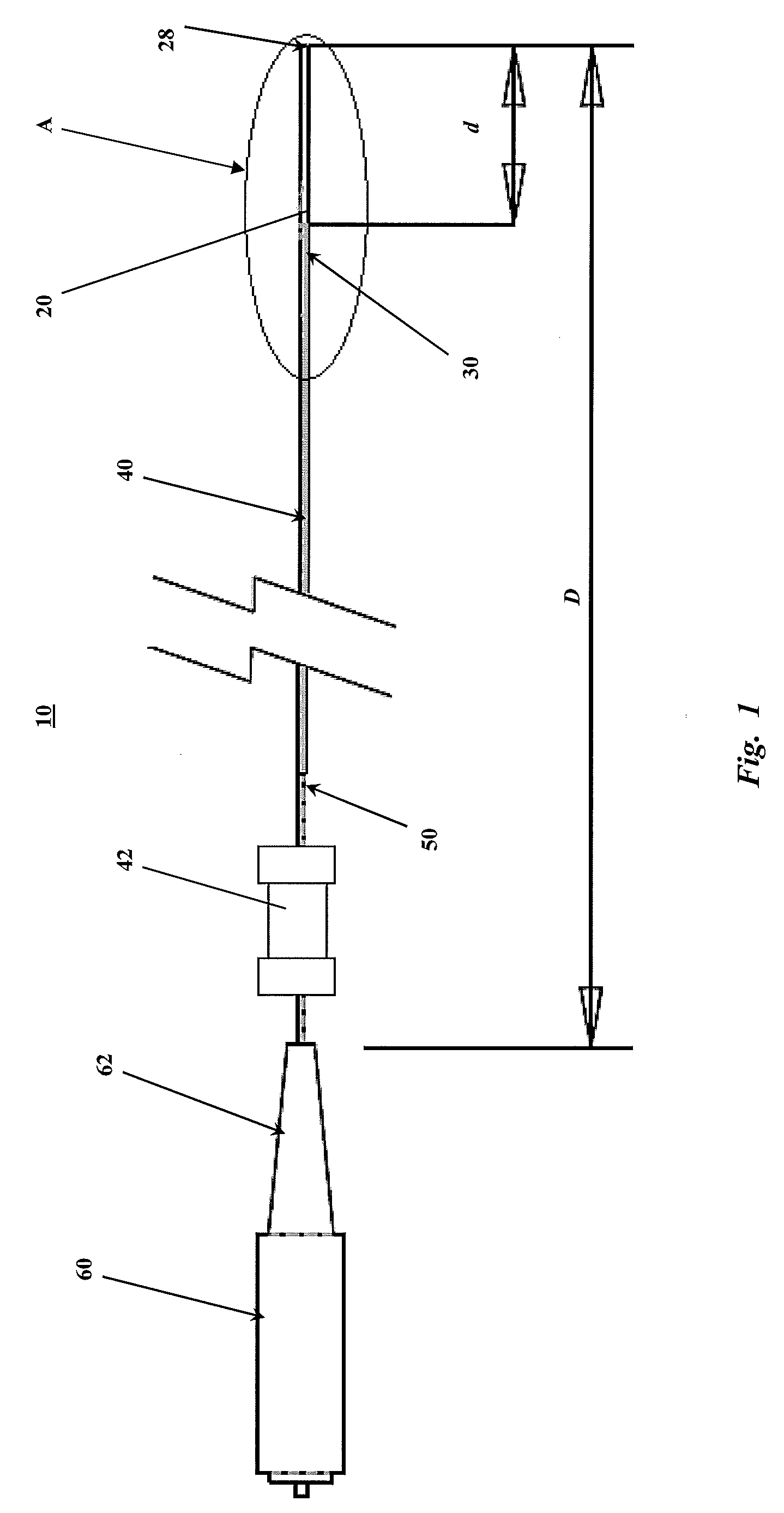
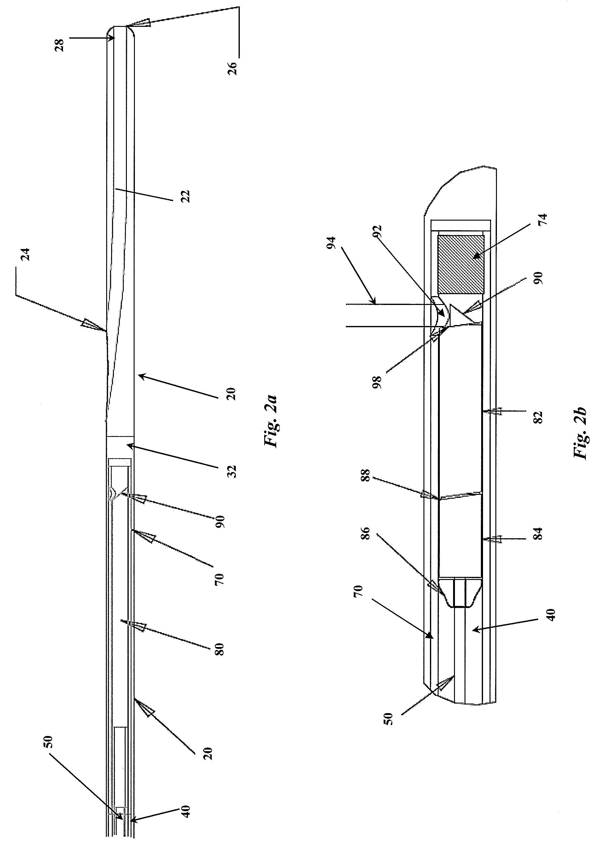
A catheter for in vivo imaging comprising a monolithic outer sheath terminating in a monolithic atraumatic tip having a guidewire lumen. The catheter for in vivo imaging comprising a rotary drive shaft that passes through a central lumen of the monolithic outer sheath to impart rotary motion.

Description

CROSS-RELATED APPLICATIONS [0001]The present application claims priority to U.S. Provisional Application Ser. No. 60 / 949,511, filed Jul. 12, 2007, incorporated by reference herein.BACKGROUND OF THE INVENTION [0002]The present invention relates generally to an apparatus for in vivo imaging. More particularly, the present invention pertains to a catheter for imaging within a mammalian body, including luminal systems, such as imaging the vasculature system, including, without limitation, cardiac vasculature, peripheral vasculature and neural vasculature.[0003]For intravascular imaging, it is difficult to achieve and maintain a uniform rotational velocity due to cables and shafts binding and / or whipping around as it is rotated in the blood vessel. Intravascular probes rotate at a nonuniform angular velocity even though the motor rotates at a uniform angular velocity. This is a problem because the angles assumed by the image processor in assembling the image vectors into the cross-sectio...

Claims


Application Information

Patent Timeline
IPC IPC(8): A61B1/04
CPCA61B5/0062A61B5/0066A61B8/4461A61B8/12A61B5/6852A61M2025/0183A61M25/0052
Inventor DICK, LARRYMILNER, THOMAS E.SIMS, DANIEL D.
Owner VOLCANO CORP
Learn More