Magnetotherapy

Inactive Publication Date: 2009-01-08
SIMPSON DOYLE DEAN
View PDF9 Cites 1 Cited by
  • Summary
  • Abstract
  • Description
  • Claims
  • Application Information

AI Technical Summary

Benefits of technology

[0003]Many different holders for magnets have been developed such as the belt disclosed by Bakst (U.S. Pat. No. 5,707,333) that can be worn around the waist of a user with the wide portion of the belt comprising an array of magnetic sources arranged by a supporting web. Gilson Woo (U.S. Pat. No. 7,097,610B2) discloses a wrap around belt to securely hold the magnets sewn-in or encased in fabric lining or adjustable Velcro type fasteners. James Snyder (U.S. Pat. No. 6,926,661B2) describes a magnet orientation assembly in combination with a mattress or mattress liner where an array of magnets of oppositely disposed poles can be maintained in a predetermined, operative orientation even as the individual moves throughout a night sleep or other rest period by using a support structure that also allows removal of magnets for cleaning, repairing or replacing. Brand N. Griffin, et al. (U.S. Pat. No. 6,554,787B1) disclosed a headband for treatment of headaches having multiple pockets at the interior of the headband for housing one or more heating, cooling, magnetic and vibratory elements to provide heat, cold, vibration and magnetism or a combination thereof to the head.
[0005]It is therefore an object of this invention to provide a simple holder for magnets used in magnetotherapy that allow movement of the magnet along a strip of material thereby allowing adjustment of position to cater to the location and position of the affected area.
[0006]It is also an object of this invention to provide a magnet holder that can add or eliminate magnets according to the intended usage.
[0007]It is a further object of this invention to provide a holder that will allow a user to easily reverse the polarity of the magnet during the course of treatment.
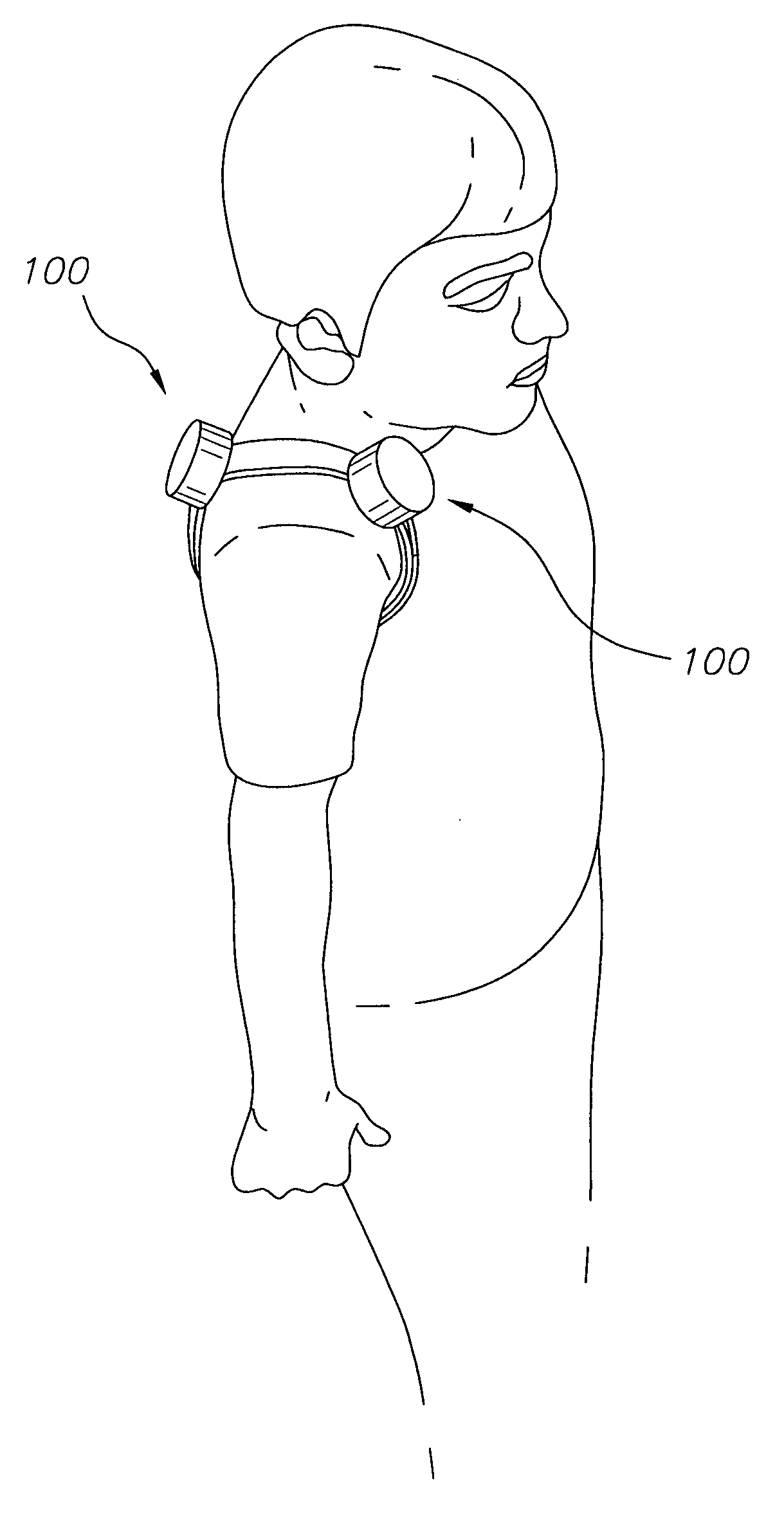
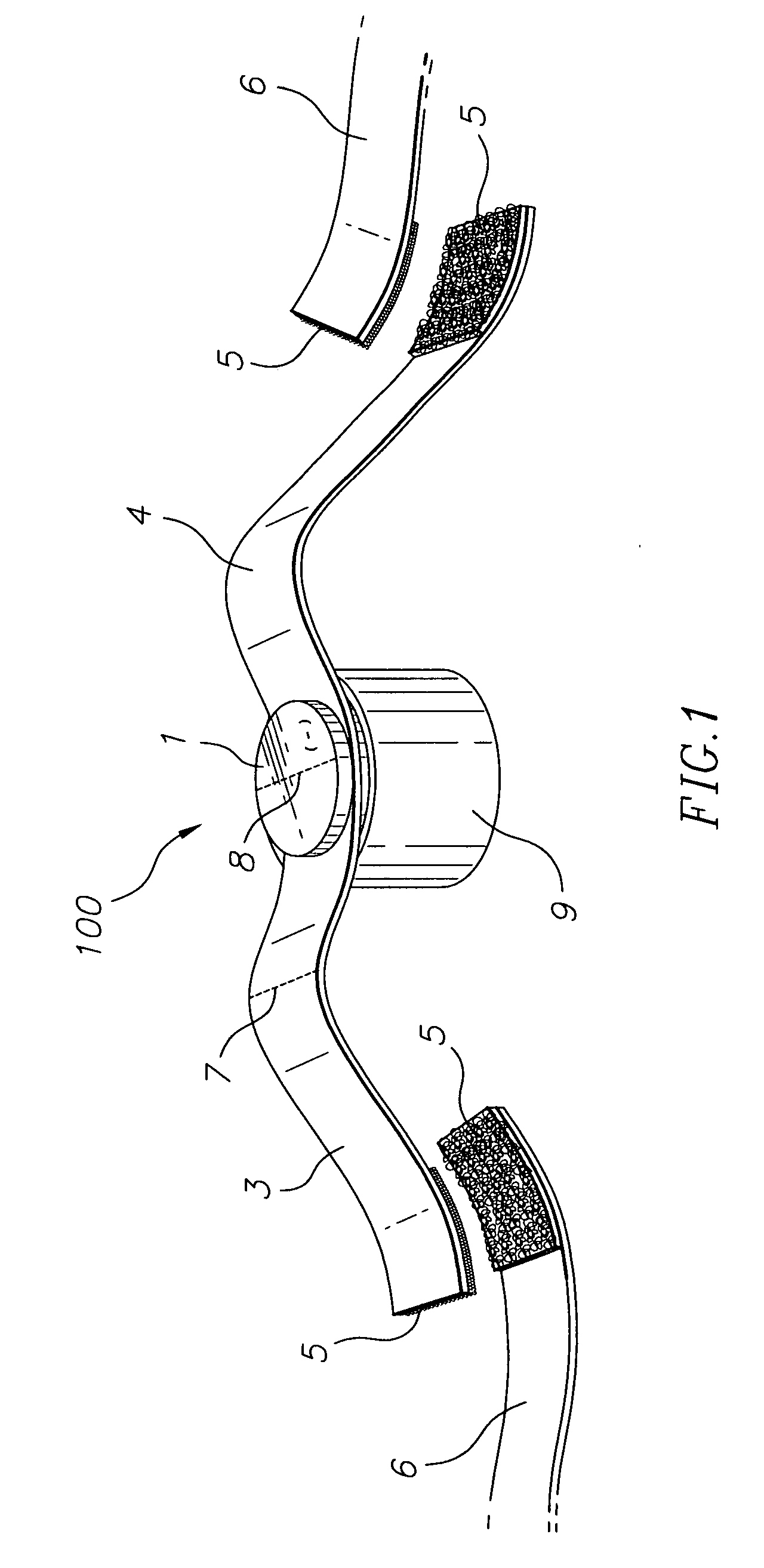
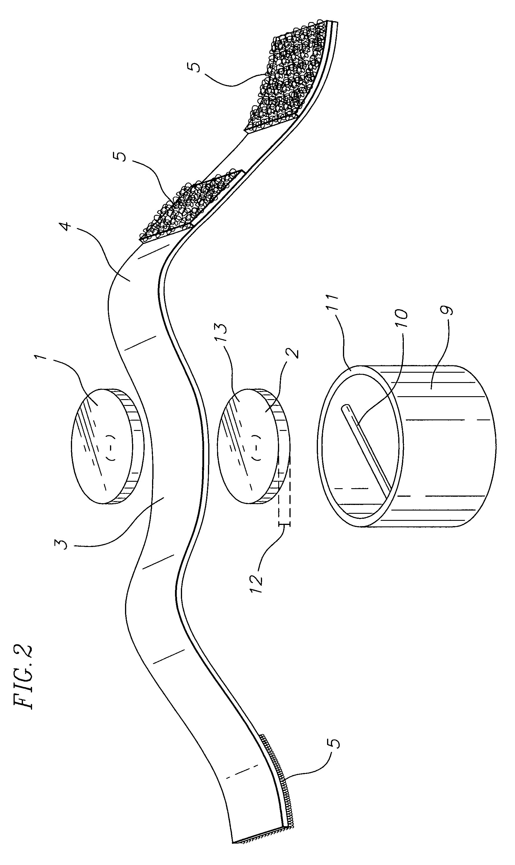
[0009]The invention relates to a magnetotherapy device for alleviating pain, healing tissues, rebuilding fractures and increasing circulation of blood. This device comprises a pair of disc shaped magnets with flat inside and outside surfaces, a top magnet and a bottom magnet attached to each other having a strap sandwiched in between, the pair of magnet movable along a length of the strap; a non-magnetic holder having a magnetic strip attaching to the bottom magnet, leaving a surface of the same polarity of the top magnet exposed, the pair of magnets removable from the holder for easily reversing and replacing the bottom magnet with the top magnet; and, a fastener means for wrapping around the strap to a part of a human body, thereby contacting the exposed surface of the magnet having the same polarity with the part of the body. A second holder having a magnetic strip attaching to the top magnet can also be provided to cover the exposed surface of the pair of magnets before storage. The non-magnetic holders can have a hollow or a solid interior under the magnetic strip. A second strap with a fastener pairing with the fastener means of the strap sandwiched between the top and bottom magnets can also be provided to lengthen the strap. Instead of just one pair, a plurality of magnetic pairs can be provided along the strap, however, it is important that the exposed surfaces of all magnetic pairs have one uniform polarity. The magnet in this device has a magnetic flux density of 2700-5000 gauss. The strap is made of fabric or leather having a varying length or varying number of fasteners along the length of the strap. In the assembled device, the strap and the top magnet are above the holder.

Problems solved by technology

In all the above designs, the magnet / s can not be easily moved to another location because each magnet is housed in a pocket or are held by support structures.
Further, the number of magnets can not be readily altered beyond the number of holders.
Also, the polarity of the magnet facing the body can not be easily reversed.

Method used


Image

  • Magnetotherapy
  • Magnetotherapy
  • Magnetotherapy

Examples


Embodiment Construction

[0025]The magnetothery device 100 is shown in FIGS. 1 and 2. It comprises of two magnets 1 and 2, the magnets, sandwiching between them, a band or strap 3. The magnets, 1 and 2 are paired, herein also referred to as magnetic pair, and held in place at the chosen location along the strap 3 because of the intensity of the attraction between the two magnets, the positive pole (+), the north-seeking pole of magnet 1 attaching to the negative pole (−), the south-seeking pole of a magnet 2 despite the presence of a non-magnetic band or strap 3 in between the two magnets. In the provided drawings, magnet 1 is the top magnet while magnet 2 is the bottom magnet. In this application, it is recommended to have the negative pole of magnet 1 at the top exposed surface while the positive pole (+) of magnet 1 is placed at the interior side opposite the negative pole. A compass can be used to determine and ensure the polarity of the exposed surface of magnet 1. The compass needle points to the sout...


PUM


Abstract

A magnetotherapy device comprising a pair of magnets having a strap in between. The position of the magnetic pair along the strap can be changed as well as the number of magnetic pairs on the strap. One of the pair of magnets is housed inside a holder while the other pair is left exposed outside of the holder. This design allows easy reversal of the magnets when a change of polarity to the affected area / s is desired. The pair of magnets have flat outside and inside surfaces for maximum contact with the affected area / s of the body. The proposed treatment using the magnetotheray device comprises contacting the affected area / s with one polarity followed by contacting the same affected area / s with another polarity, different from the polarity of the previous contact.

Description

[0001]Magnets have been used to relieve pain based on the belief that nerve impulses associated with pain are carried to the brain and magnetic therapy or magnetotherapy can impede the flow of these nerve impulses. Consequently, the magnet or magnets are placed at these areas which is / are not necessarily over the affected site or sites. For example, a migraine is recommended to be treated by placing the magnet over the chin while a shoulder pain is recommended to be treated by placing a magnet on the front and behind the shoulder. It has also been proposed that pain is relieved because the human blood, being replete with ions and electrolytes which are charged molecules, particles and the like, experience a force, including an aligning force when moving through a magnetic field. This motion causes generation of heat which widen the blood vessels and thereby allow increased flow of blood through them and cause it to gently churn. Magnets have also been used for its demonstrated effec...

Claims


Application Information

Patent Timeline
IPC IPC(8): A61N2/08
CPCA61N2/06
Inventor SIMPSON, DOYLE DEAN
Owner SIMPSON DOYLE DEAN
Why Eureka
Try Eureka