Bearing for motorized fuel pump
a technology of motorized fuel and pump, which is applied in mechanical equipment, transportation and packaging, chemical equipment and processes, etc., can solve the problems of low quality gasoline, abrasion resistance, and different quality of liquid fuel used, and achieve excellent corrosion resistance, abrasion resistance, and high strength
Active Publication Date: 2009-01-08
AISAN IND CO LTD +1
View PDF2 Cites 25 Cited by
- Summary
- Abstract
- Description
- Claims
- Application Information
AI Technical Summary
Benefits of technology
[0015]The bearing of the present invention can demonstrates excellent corrosion resistance, abrasion resistance, and high strength when used in a motorized fuel pump for an engine that uses normal liquid fuel, but also wi
Problems solved by technology
However, the quality of the liquid fuel used differs in different parts of the world, and many regions use low quality gasoline.
However, at present, although conventional bearings made of Cu-based
Method used
View moreImage
Smart ImageViewing Examples
Examples
 PUM
| Property | Measurement | Unit |
|---|---|---|
| Fraction | aaaaa | aaaaa |
| Percent by mass | aaaaa | aaaaa |
| Percent by mass | aaaaa | aaaaa |
Abstract
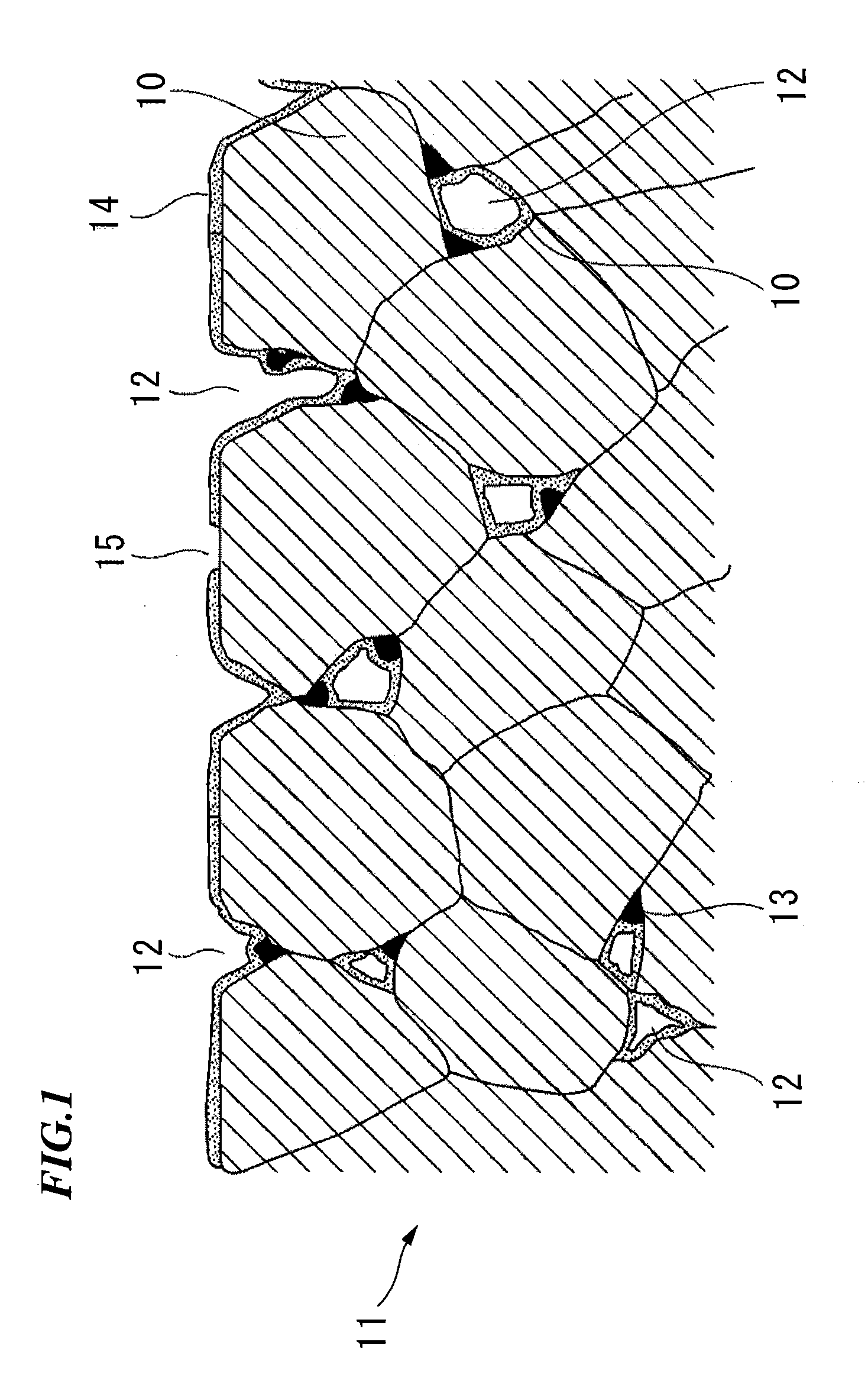
A bearing for a motorized fuel pump is made of a Cu—Ni based sintered alloy, composed of: 21 to 35% by mass of Ni, 5 to 12% by mass of Sn, 3 to 7% by mass of C, 0.1 to 0.8% by mass of P, and the balance of Cu and inevitable impurities. A matrix of the bearing is formed with pores with a porosity of 8 to 18%, and the P component is predominantly included at the grain boundary, and free graphite is distributed along the insides of open pores that are open to the surface and extending into the bearing. In this bearing, a Sn rich alloy layer containing equal to or more than 50% by mass of Sn is formed on the insides of the open pores and near openings of the open pores.
Description
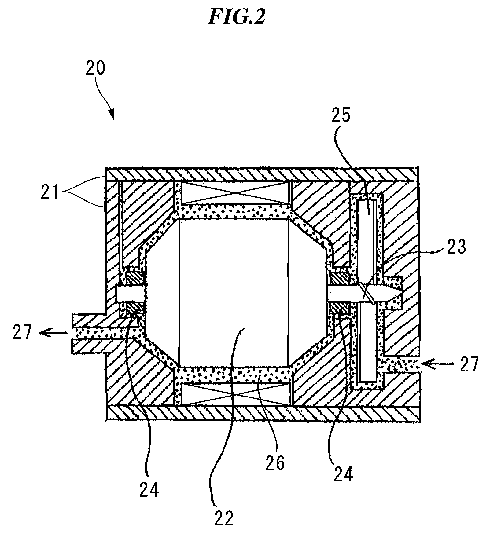
CROSS REFERENCE TO RELATED APPLICATIONS[0001]This is a U.S. national phase application under 35 U.S.C. § 371 of International Patent Application No. PCT / JP2005 / 300521 filed Jan. 17, 2006, and claims the benefit of Japanese Application No. 2005-009989, filed Jan. 18, 2005. The International Application was published in Japanese on Jul. 27, 2006 as International Publication No. WO 2006 / 077826 under PCT Article 21(2) the content of which are incorporated herein in their entirety.TECHNICAL FIELD[0002]The present invention relates to a bearing for a motorized fuel pump, made of a Cu—Ni based sintered alloy.[0003]Conventionally, an engine that uses a liquid fuel such as gasoline or light oil is typically equipped with a motorized fuel pump. For example, FIG. 2 shows an outline cross-sectional side view of a known motorized fuel pump 20 for use with a gasoline engine.[0004]In the motorized fuel pump 20 shown in FIG. 2, a rotating shaft 23 fixed to both ends of a motor 22 is supported by be...
Claims
Login to View More Application Information
Patent Timeline
 IPC IPC(8): B32B5/18B32B15/02
CPCB22F2998/00Y10T428/12708C22C1/0425C22C1/0433C22C9/06C22C13/00B22F2999/00Y10T428/12042Y10T428/12903Y10T428/12715F16C33/121B22F3/11B22F3/10B22F2207/01B22F2201/016F16C33/16F16C33/06
Inventor SHIMIZU, TERUOMARUYAMA, TSUNEONARISAKO, HIDEKIHAZAMA, TADASHI
Owner AISAN IND CO LTD
Features
- R&D
- Intellectual Property
- Life Sciences
- Materials
- Tech Scout
- Unparalleled Data Quality
- Higher Quality Content
- 60% Fewer Hallucinations
Learn More Browse by: Latest US Patents, China's latest patents, Technical Efficacy Thesaurus, Application Domain, Technology Topic, Popular Technical Reports.
© 2025 PatSnap. All rights reserved.Legal|Privacy policy|Modern Slavery Act Transparency Statement|Sitemap|About US| Contact US: help@patsnap.com


