
Optical system for enhanced vision

a technology of enhanced vision and optical system, applied in the field of peripheral vision, can solve the problems of difficult adjustment, cumbersome, complicated motorcycles and other vehicles, etc., and achieve the effects of eliminating accidents, enlarging peripheral vision, and high image quality

Inactive Publication Date: 2009-01-08
REICHERT ABRAHAM
View PDF13 Cites 0 Cited by
  • Summary
  • Abstract
  • Description
  • Claims
  • Application Information

AI Technical Summary

Benefits of technology

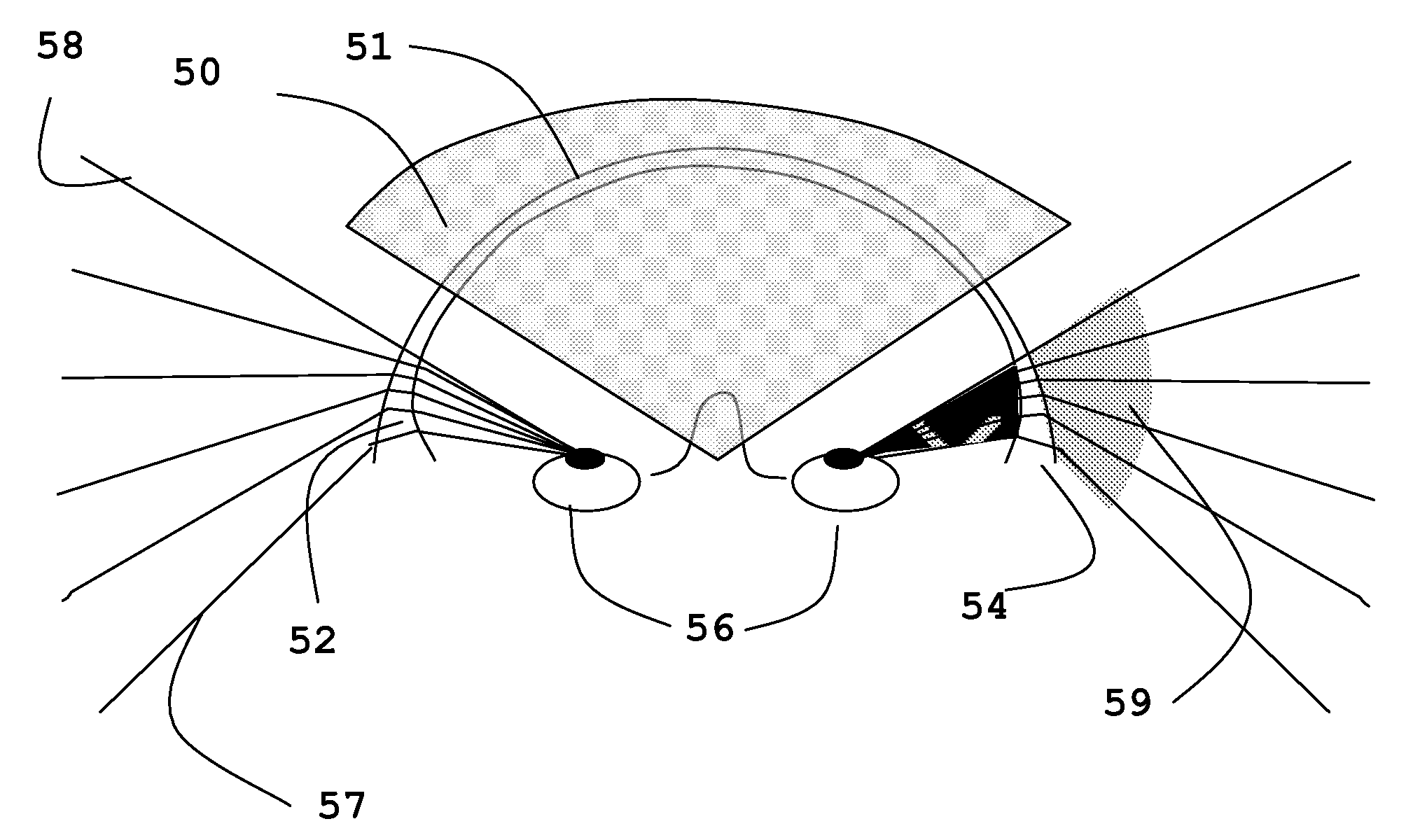
[0004]The optical system increases the human peripheral vision beyond 200° homogenously and without using any mirrors. One embodiment of the invention adds a graduated optical or prismatic power to a visor or glasses (e.g., eyeglasses, sunglasses, etc.) at the edge of the peripheral FOV, for example, higher than 70°. The optical power is negative so the normal 200° FOV can become much larger, increasing up to 240° or even more. Since the optical acuity of the human eye at the edge of the FOV is very low, there is no need for high image quality.
[0005]The optical power is in the form of an anamorphic optical element (also referred to as a distorting optical element), which is added to the edge of the FOV can be refractive or diffractive in nature. For example, the invention can be carried out with a segment of a diverging optical element, a segment of a diverging Fresnel element, a segment of a diffractive diverging optical element or a graduated grating or any combination thereof (as described with reference to FIGS. 5-7D below). The optical element of the invention can be added to a vision device worn by a user, such as but not limited to, helmets, visors, glasses or contact lenses, for example, for enlarging peripheral vision. (The terms “vision device” and “visor” will be used interchangeably as a general term throughout the specification and claims for any vision device worn by a user.) The advantages of the invention are numerous. For example, it enables motorcycle riders to see more than 200° without head turning, thereby eliminating accidents and reducing the danger of driving. It is very important to fighter aircraft pilots. In general, enlarged peripheral vision improves spatial orientation in space.

Problems solved by technology

In cars it is very simple to implement these mirrors, while in motorcycles and other vehicles it is more complicated.
They tend to be cumbersome and hard to adjust.

Method used


Image

  • Optical system for enhanced vision
  • Optical system for enhanced vision
  • Optical system for enhanced vision

Examples


Embodiment Construction

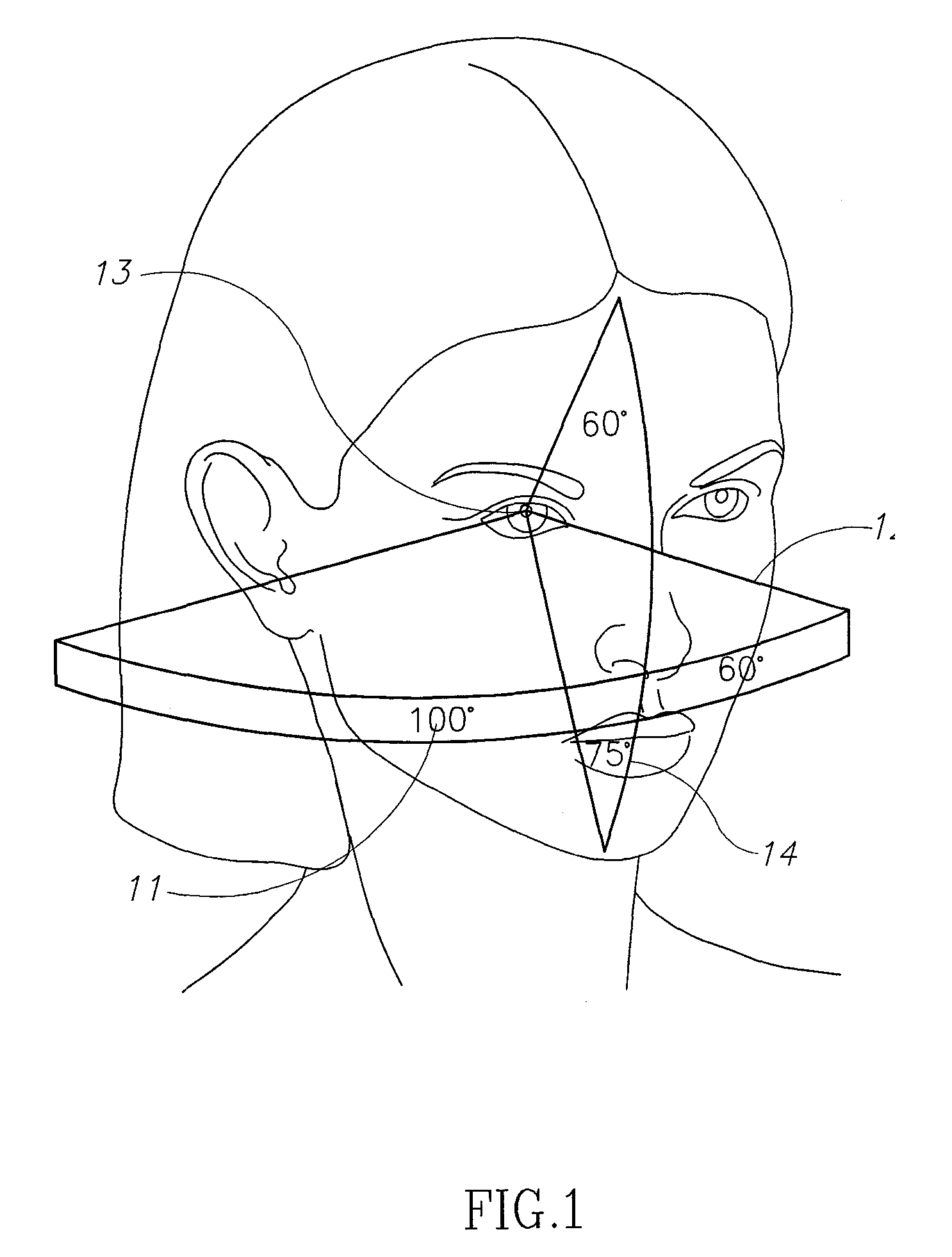
[0023]Reference is now made to FIG. 1, which illustrates a Field of View (FOV) of a human eye. The vertical upper maximum FOV (13) is about 60°, and the lower FOV (14) is about 70°. The horizontal FOV to the right (11) is about 100° and the FOV to the left (12) is about 60°.

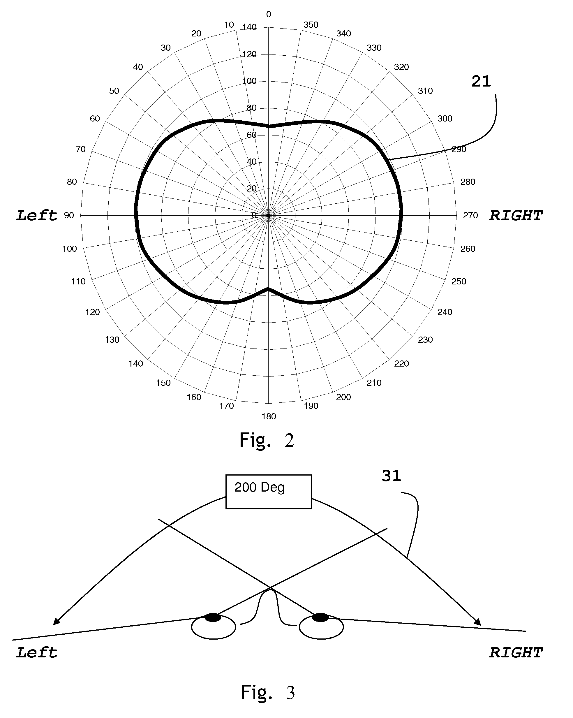
[0024]Reference is now made to FIG. 2, which is a schematic polar diagram showing the total FOV of both eyes. The horizontal total FOV is about 200°. FIG. 3 illustrates the FOV in the horizontal plane of both eyes.

[0025]The present invention provides structure for stretching the total FOV, such as in the horizontal space. FIG. 4 illustrates a polar diagram of the normal FOV (41) and the stretched FOV (42), which has been stretched with an anamorphic segment constructed in accordance with the present invention (described below). FIG. 4 illustrates the area of the anamorphic segment at the right zone (43) and at the left zone (44).

[0026]Reference is now made to FIG. 5A, which illustrates anamorphic segments (52, 54...


PUM


Abstract

An optical system including a vision device wearable by a user for seeing objects in a field of view (FOV), the vision device comprising a front section with a normal distortion of rays passing therethrough, and an anamorphic optical element extending from the front section that distorts rays passing therethrough with an extended distortion greater than that of the front section and which enlarges the FOV.

Description

FIELD OF THE INVENTION[0001]The present invention relates generally to peripheral vision, and more specifically to methods and apparatus for increasing the human peripheral field of view.BACKGROUND OF THE INVENTION[0002]Enlarging peripheral vision is necessary for many applications, such as motorcycle or bicycle riders, divers, sport players, etc. Human vision has the ability to detect moving objects up to 100° off the direct view or 200° with both eyes, but is limited beyond this range. To overcome this limitation, devices such as side view mirrors are used, which have a small field of view (FOV) and enable seeing objects behind the back. In cars it is very simple to implement these mirrors, while in motorcycles and other vehicles it is more complicated. It is also known to place rear view mirrors in helmets and eyeglasses. Rear view mirrors have drawbacks. They obscure some of the forward FOV. The reflected FOV is very small. They tend to be cumbersome and hard to adjust.SUMMARY O...

Claims


Application Information

Patent Timeline
Patent Type & Authority Applications(United States)
IPC IPC(8): G02B13/08A61F9/04G02C7/04
CPCG02C2202/20G02C7/02
Inventor REICHERT, ABRAHAM
Owner REICHERT ABRAHAM
Learn More