
Method and Apparatus for a High Bandwidth Oscilloscope Utilizing Multiple Channel Digital Bandwidth Interleaving

a technology of digital bandwidth and oscilloscope, applied in the direction of digital computer details, instruments, code conversion, etc., can solve the problems of increasing the cost of ic development, the difficulty of utilizing the fastest ic design process, and the dilemma of dso performan

Active Publication Date: 2009-01-01
TELEDYNE LECROY
View PDF40 Cites 48 Cited by
  • Summary
  • Abstract
  • Description
  • Claims
  • Application Information

AI Technical Summary

Problems solved by technology

These desired increases in DSO performance produce a dilemma because the bandwidth of the DSO is mostly related to the speed of the front-end amplifiers and analog-to-digital converters (ADCs) used therein.
In other words, the DSO is preferably built in and using the same processes as the chips that the DSO is designed to test.a. The fastest IC design processes are expensive and difficult to utilize when they are first introduced, especially for low volume IC production.
ASIC development has been becoming increasingly expensive, almost to a point whereby the huge development costs cannot be recaptured in a relatively low volume production area, such as the oscilloscope market.
Additionally, the development time for higher performance ASICs and the supporting hardware can be prohibitively long and cumbersome which can extensively delay the time to market for a product.

Method used


Image

  • Method and Apparatus for a High Bandwidth Oscilloscope Utilizing Multiple Channel Digital Bandwidth Interleaving
  • Method and Apparatus for a High Bandwidth Oscilloscope Utilizing Multiple Channel Digital Bandwidth Interleaving
  • Method and Apparatus for a High Bandwidth Oscilloscope Utilizing Multiple Channel Digital Bandwidth Interleaving

Examples


Embodiment Construction

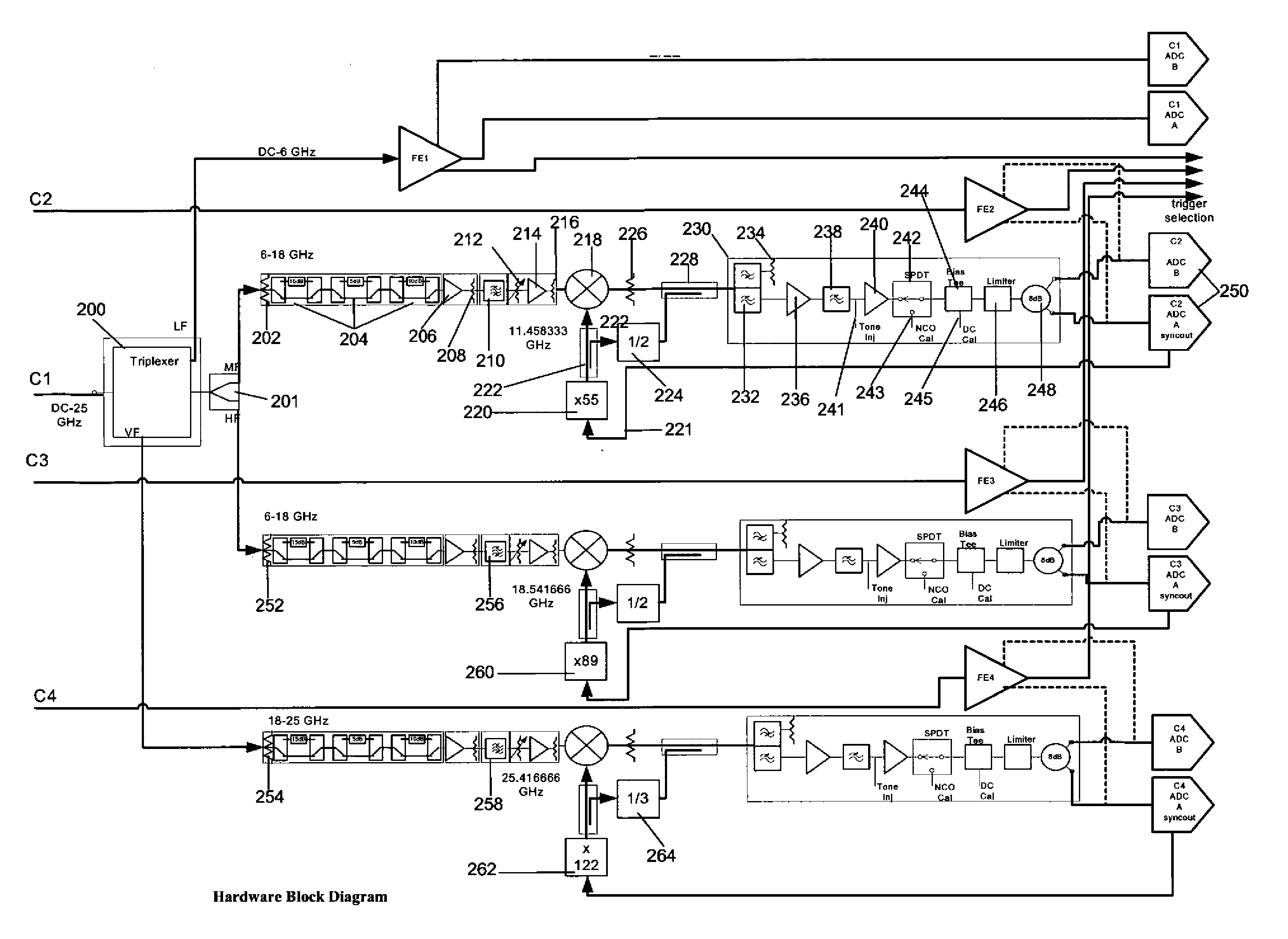
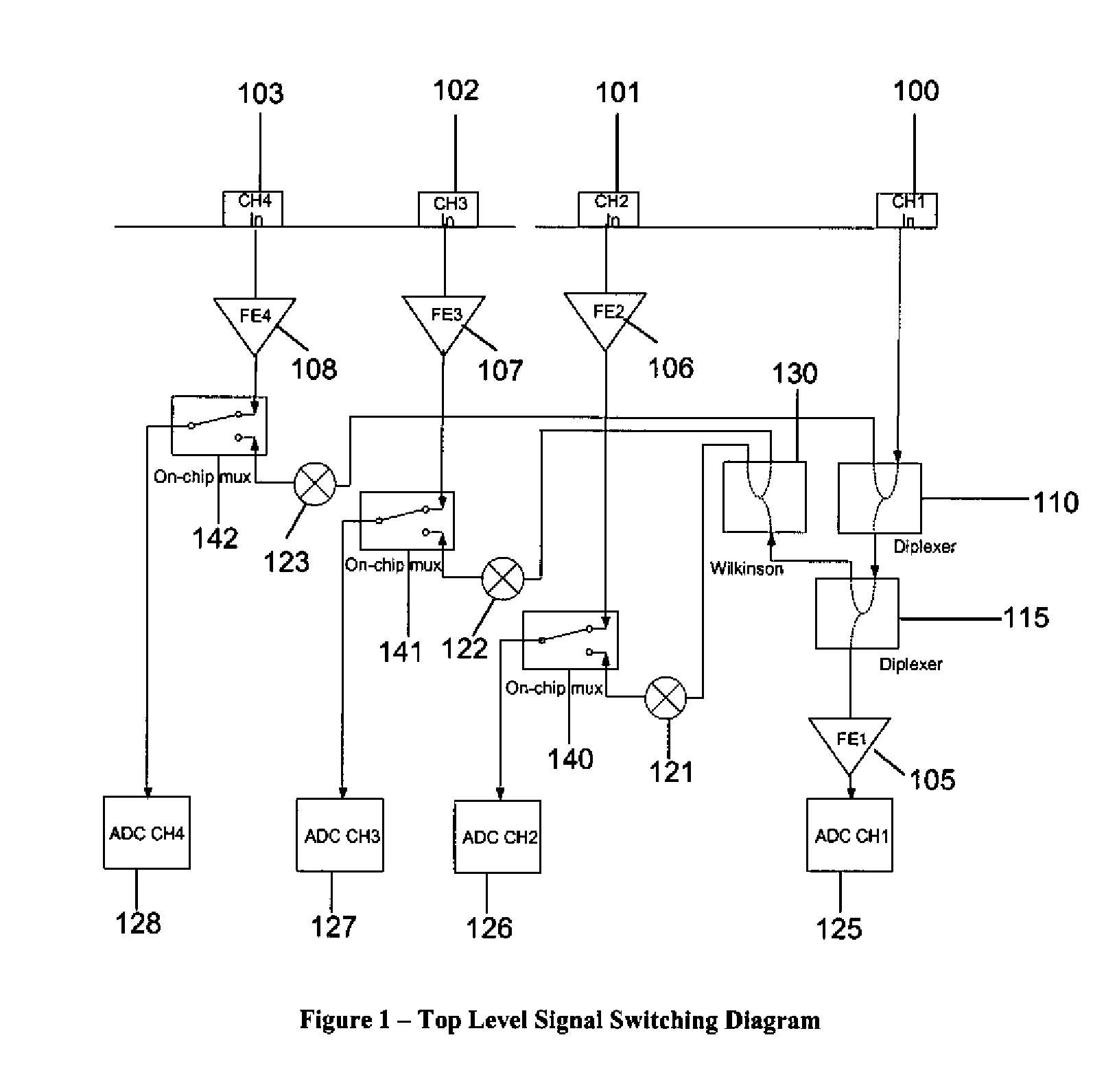
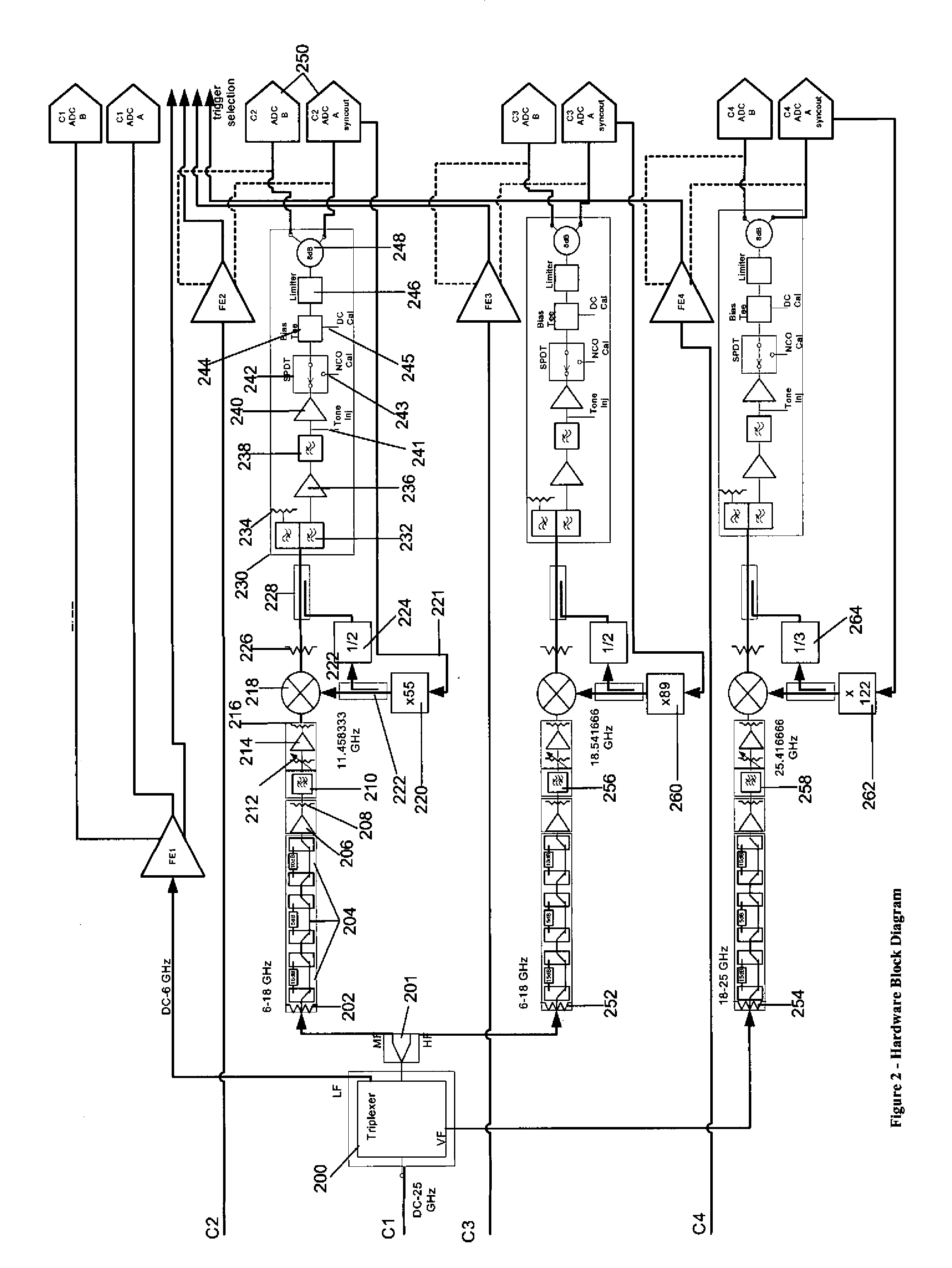
[0061]FIG. 1 shows a block diagram of a DBI enabled oscilloscope constructed in accordance with a preferred embodiment of the invention. This diagram shows a single channel DBI implementation. In this preferred implementation, oscilloscope channels 1 [101], 2 [102], 3 [103], and 4 [104] can be selectively grouped together in a sequential order to form a single high bandwidth channel. A user can operate the oscilloscope in a non-combined configuration with four independent 6 GHz channels or can combine up to four channels into a single 25 GHz channel. There are other selectable grouping schemes where the user can choose two 6 GHz channels and one 11 GHz channel that is created by grouping channels 1 and 2, or one 6 GHz channel and one 18 GHz channel that is created by grouping channels 1, 2, and 3. While not particularly shown, two 11 GHZ channels may also be selected by a user. These channel groupings are illustrated in FIG. 12. For the most general discussion, the implementation of...


PUM


Abstract

A method of digitizing an analog signal is provided, comprising the steps of separating the analog signal spanning a frequency range into a plurality of frequency bands, each frequency band spanning a corresponding predefined frequency range, at least a portion of each of the plurality of corresponding frequency ranges not overlapping any other of the plurality of corresponding predefined frequency ranges and then translating at least one of the signals in the plurality of frequency bands to a lower frequency band in accordance with a local oscillator and digitizing the at least one translated signal with digitizing elements having a frequency range less than the analog signal frequency range. A fixed relationship of the phase of the local oscillator and a repetitive signal generated in accordance with a writing to a circular buffer of the digitized representation of the at least one of the plurality of frequency bands is then defined. Signals corresponding to the other of the plurality of frequency bands are digitized and written to corresponding circular buffers in accordance with one or more corresponding local oscillators. Finally, a digital representation of the analog signal is formed from the digitized signals, the digital representation substantially spanning the frequency range of the analog signal, and the digital representation is stored in a computer readable medium.

Description

CROSS-REFERENCE TO RELATED APPLICATIONS[0001]This application claims the benefit under of U.S. Provisional Patent Application Ser. No. 60 / 972,091 filed May 1, 2007 titled “OSCILLOSCOPE” the contents thereof being incorporated herein by reference. This application is also a Continuation-In-Part application of U.S. patent application Ser. No. 12 / 102,946 filed Apr. 15, 2008 titled “High Bandwidth Oscilloscope”, currently pending which is a continuation of U.S. patent application Ser. No. 11 / 729,606, filed Mar. 29, 2007 by Peter Pupalaikis et al., entitled “High Bandwidth Oscilloscope”, currently pending, which in turn is a continuation application of U.S. patent application Ser. No. 11 / 281,075, filed Nov. 17, 2005 by Peter Pupalaikis et al., entitled “High Bandwidth Oscilloscope”, now U.S. Pat. No. 7,219,037. The '037 patent in turn claims the benefit of U.S. Provisional Patent Application 60 / 629,050, filed Nov. 18, 2004 by Pupalaikis and entitled “High Bandwidth Oscilloscope,” ii) U.S...

Claims


Application Information

Patent Timeline
Patent Type & Authority Applications(United States)
IPC IPC(8): H03M1/12
CPCG01R23/16G01R13/0272
Inventor LAMARCHE, FRANCOISJOSHI, LAXMIKANTSUREKA, ANIRUDH
Owner TELEDYNE LECROY
Learn More