Flow rate measuring apparatus
a technology of flow rate and measuring apparatus, which is applied in the direction of liquid/fluent solid measurement, volume metering, instruments, etc., can solve the problems of flow rate detection error and flow rate detection error
- Summary
- Abstract
- Description
- Claims
- Application Information
AI Technical Summary
Benefits of technology
Problems solved by technology
Method used
Image
Examples
embodiment 1
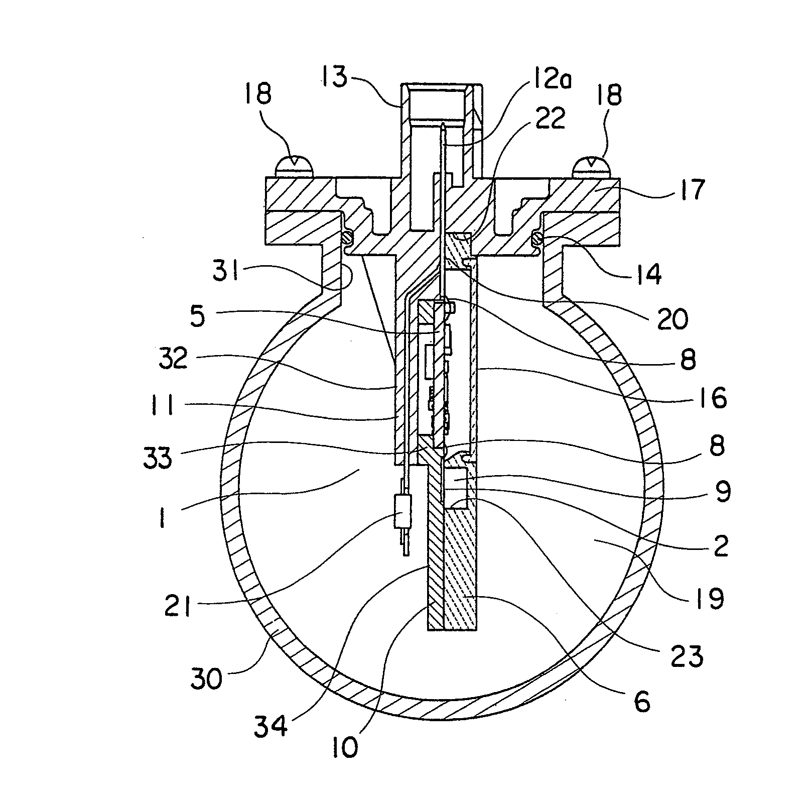
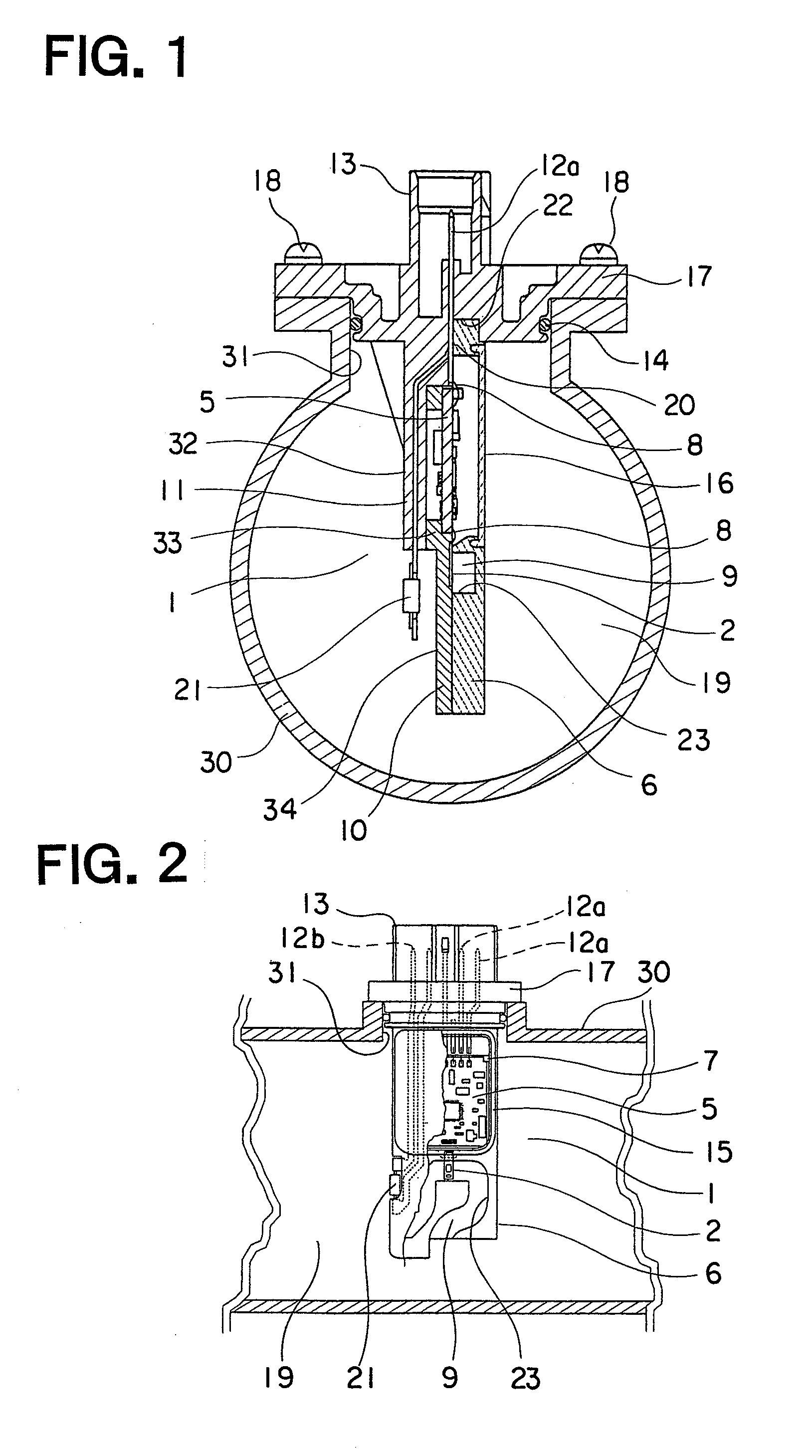
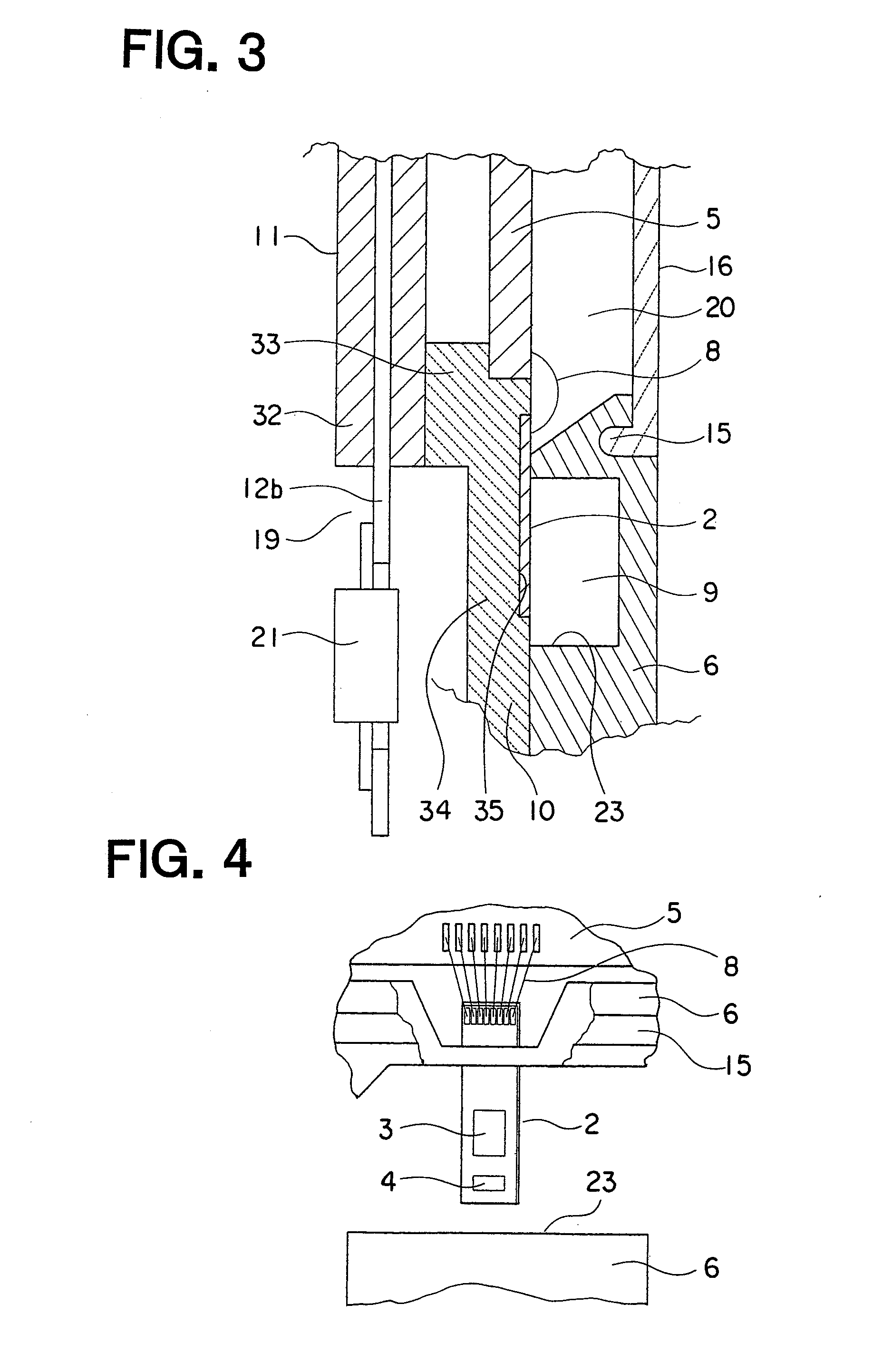
[0052]Referring to the drawings and first to FIG. 1, there is shown a cross sectional side view of a flow rate measuring apparatus according to a first embodiment of the present invention. FIG. 2 is a partially cut-away front elevational view of the flow rate measuring apparatus of FIG. 1. FIG. 3 is an enlarged view of essential portions of the flow rate measuring apparatus of FIG. 1, and FIG. 4 is an enlarged view of essential portions of the flow rate measuring apparatus of FIG. 2.
[0053]An intake pipe 30 of the internal combustion engine has an insertion hole 31 formed therein, and the flow rate measuring apparatus, generally designated at reference numeral 1, is inserted into the insertion hole 31 and installed on the intake pipe 30.
[0054]This flow rate measuring apparatus 1 includes a base 11, a plate 10 that is attached or bonded to the base 11 along a flow direction of air in the form of a fluid to be measured, a flow rate detection element 2 that is formed on the plate 10 so ...
embodiment 2
[0081]FIG. 10 is a cross sectional side view that shows a flow rate measuring apparatus 1 according to a second embodiment of the present invention, and FIG. 11 is a partially cut-away front elevational view of the flow rate measuring apparatus 1 of FIG. 10.
[0082]In the second embodiment of the present invention, a base 11 and a plate 10 are integrally formed with each other by the use of the same PBT resin. The other construction of this second embodiment is similar to that of the first embodiment.
[0083]According to the flow rate measuring apparatus of this second embodiment, advantageous effects similar to those of the first embodiment can be achieved. In addition, the process of positioning or aligning the plate 10 and the base 11 with each other becomes unnecessary, and at the same time, based on the thus integrated component parts of the plate 10 and the base 11, it is possible to assemble the respective component parts including the circuit board 5, the housing 6 and the cover...
embodiment 3
[0084]FIG. 12 is a cross sectional side view that shows a flow rate measuring apparatus 1 according to a third embodiment of the present invention, and FIG. 13 is a partially cut-away front elevational view of the flow rate measuring apparatus 1 of FIG. 12.
[0085]In this third embodiment of the present invention, a base main body 32 of a base 11 and a flange 17 are formed as separate members, respectively. The base main body 32, a plate 10, a circuit board 5, a housing 6 and a cover 16, which are laminated one over another, have their relative positions to the flange 17 located at a radially outer side thereof in comparison with the first embodiment. The other construction of this third embodiment is similar to that of the first embodiment.
[0086]In this third embodiment, the same effects as those in the first embodiment can be achieved, and the wire 8 electrically connecting between the circuit board terminal 12a and the circuit board 5 is arranged at a fixed side of the vibration of...
PUM
 Abstract
Description
Claims
Application Information
 - R&D
- Intellectual Property
- Life Sciences
- Materials
- Tech Scout
- Unparalleled Data Quality
- Higher Quality Content
- 60% Fewer Hallucinations
Browse by: Latest US Patents, China's latest patents, Technical Efficacy Thesaurus, Application Domain, Technology Topic, Popular Technical Reports.
© 2025 PatSnap. All rights reserved.Legal|Privacy policy|Modern Slavery Act Transparency Statement|Sitemap|About US| Contact US: help@patsnap.com


