
System and method for accuracy verification for image based surgical navigation

Active Publication Date: 2008-12-25
STRYKER EURO OPERATIONS HLDG LLC
View PDF11 Cites 189 Cited by
  • Summary
  • Abstract
  • Description
  • Claims
  • Application Information

AI Technical Summary

Benefits of technology

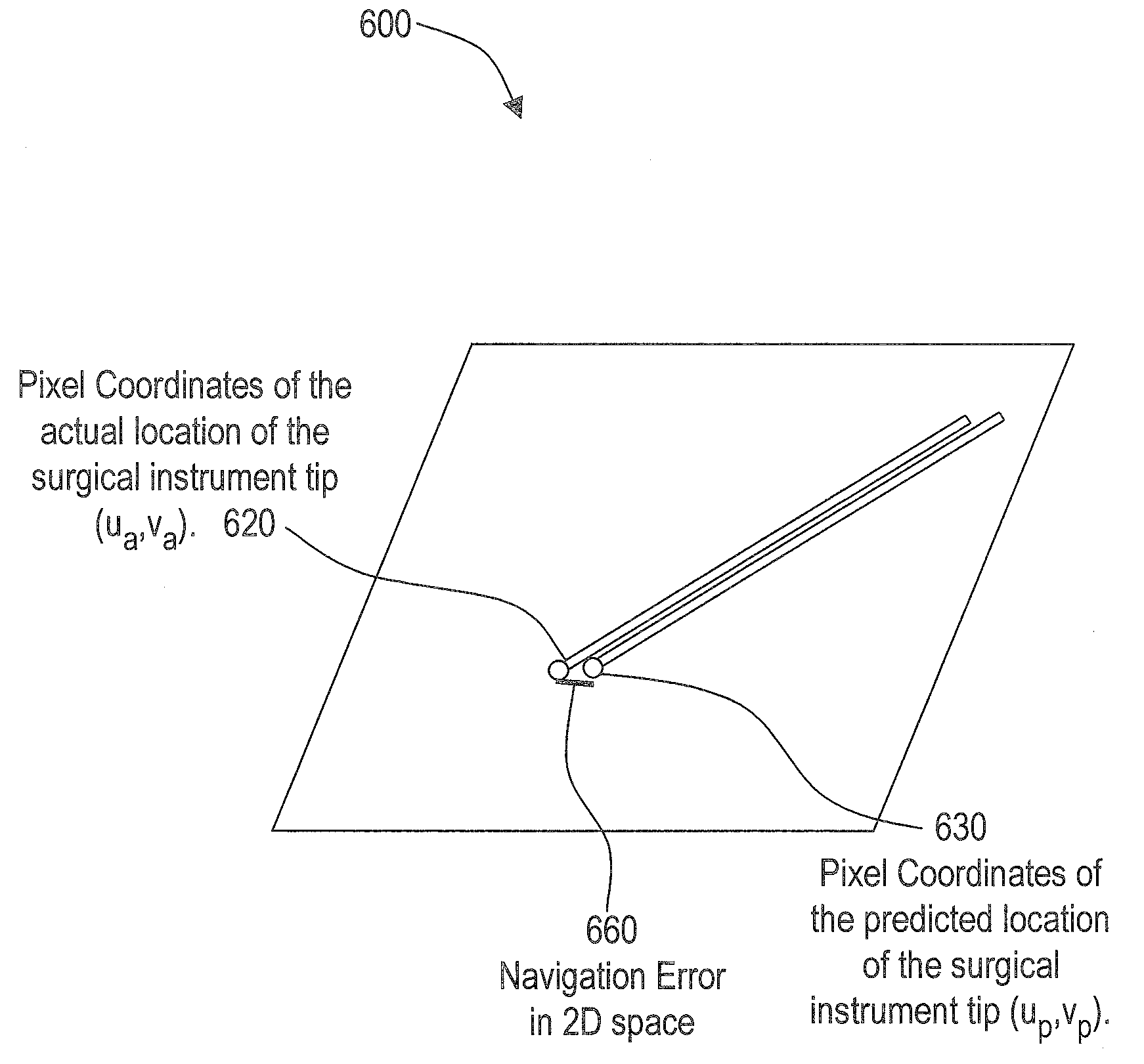
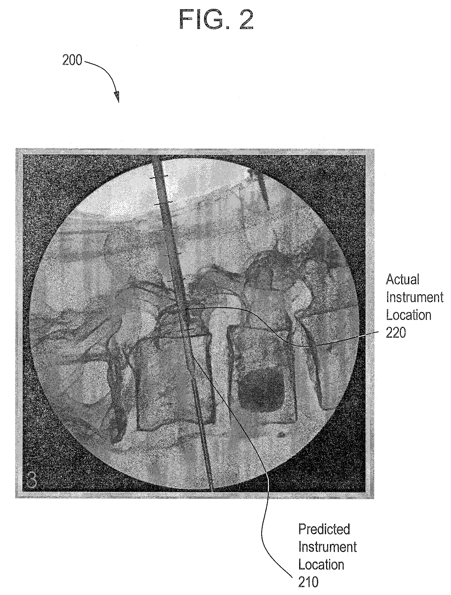
[0009]Certain embodiments of the present invention may include a method for assessing the accuracy of a surgical navigation system. The method may include acquiring an X-ray image that captures a surgical instrument. The method may also include segmenting the surgical instrument in the X-ray image. In an embodiment, the segmenting the surgical instrument in the X-ray image may be performed using edge detection or pattern recognition. The method may also include computing the distance between the predicted location of the surgical instrument tip and the actual location of the surgical instrument tip. The distance between the predicted location of the surgical instrument tip and the actual location of the surgical instrument tip may be compared with a threshold value. If the distance between the predicted location of the surgical instrument tip and the actual location of the surgical instrument tip is greater than a threshold value, a user may be alerted. The computation of

Problems solved by technology

The computation of the distance between the predicted location of the surgical instrument tip and the actual location of the surgical instrument tip may be the navigation error in a 3D navigation volume.
The computation routine for computing the distance between the predicted location of the surgical instrument tip and the actual location of the surgical instrument tip may be the navigation error in a 3D navigation volume.
The computation routine for computing the distance between the predicted location of the surgical instrument tip and the actual location of the surgical instrument tip may be the navigation error in a 2D image.

Method used


Image

  • System and method for accuracy verification for image based surgical navigation
  • System and method for accuracy verification for image based surgical navigation
  • System and method for accuracy verification for image based surgical navigation

Examples


Embodiment Construction

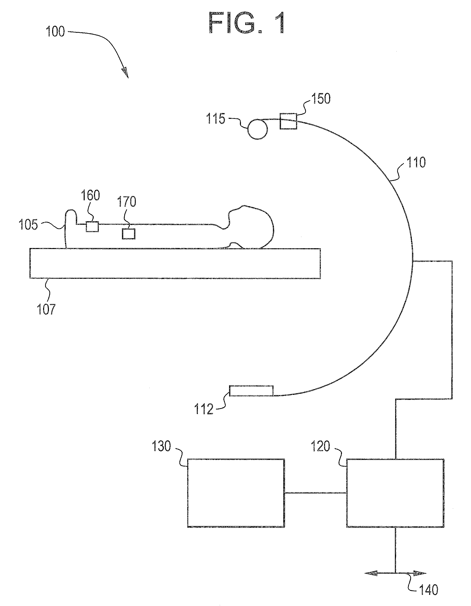
[0022]FIG. 1 illustrates a system 100 that may be used for image guided surgery in accordance with an embodiment of the present invention. The system 100 illustrates, as an example of a medical imaging unit, a C-arm unit 110. The medical imaging unit, however, may be other medical imaging equipment, such as an ultrasound unit, for example. Accordingly, any medical imaging equipment may be used.

[0023]The C-arm unit 110 is connected to a computer unit 120. The connection between the C-arm unit 110 and the computer unit 120 may be wired or wireless. The computer unit 120 may be any equipment or software that permits electronic medical images, such as x-rays, ultrasound, CT, MRI, EBT, MR, or nuclear medicine for example, to be electronically acquired, stored, or transmitted for viewing and operation. The computer unit 120 may receive input from a user. The computer unit 120 represents, in general, equipment and software. The actual physical computer units may be separate units, part of ...


PUM


Abstract

Certain embodiments of the present invention provide for a system and method for assessing the accuracy of a surgical navigation system. The method may include acquiring an X-ray image that captures a surgical instrument. The method may also include segmenting the surgical instrument in the X-ray image. In an embodiment, the segmenting may be performed using edge detection or pattern recognition. The distance between the predicted location of the surgical instrument tip and the actual location of the surgical instrument tip may be computed. The distance between the predicted location of the surgical instrument tip and the actual location of the surgical instrument tip may be compared with a threshold value. If the distance between the predicted location of the surgical instrument tip and the actual location of the surgical instrument tip is greater than the threshold value, the user may be alerted.

Description

BACKGROUND OF THE INVENTION[0001]The present invention generally relates to a system and method for improving the navigation accuracy of an electromagnetic navigation system for use with medical applications. Particularly, the present invention relates to a system and method for verifying the accuracy of a surgical navigation system.[0002]Electromagnetic type navigation systems are useful in numerous applications. One application of particular use is in medical applications, and more specifically, image guided surgery. Typical image guided surgical systems acquire a set of images of an operative region of a patient's body and track a surgical tool or instrument in relation to one or more sets of coordinates. At the present time, such systems have been developed or proposed for a number of surgical procedures such as brain surgery and arthroscopic procedures on the knee, wrist, shoulder or spine, as well as certain types of angiography, cardiac or other interventional radiological pr...

Claims


Application Information

Patent Timeline
IPC IPC(8): A61B5/05
CPCA61B5/06A61B6/12G06T7/60A61B5/062
Inventor HAMADEH, MOHAMED ALI
Owner STRYKER EURO OPERATIONS HLDG LLC
Learn More