Bio cell cleaning centrifuge and bio cell cleaning rotor used in the same

Inactive Publication Date: 2008-12-25
HITACHI KOKI CO LTD
View PDF8 Cites 22 Cited by
  • Summary
  • Abstract
  • Description
  • Claims
  • Application Information

AI Technical Summary

Benefits of technology

[0027]Another object of the present invention is to provide a bio cell cleaning centrifuge and a bio cell cleaning rotor which can obtain a bio cell test result which is high in reliability by improving a bio cell cleaning advantage.
[0035]According to the above-mentioned configuration, the plural test tube holders hold the test tubes in the inclined state from the vertical state so that the center axis of each test tube is inclined from the vertical line direction along the rotation axis of the rotor to the horizontal line direction along the tangent of the circle formed by the circular array of the test tube holders. Therefore, in the cleaning liquid injection step, the equal amount of cleaning liquid can be supplied into the many test tubes; and in the supernatant discharge step, the supernatant can be discharged from the many test tubes sufficiently and equally. Hereby, a bio cell cleaning advantage can be improved, so that it is possible to provide a bio cell cleaning centrifuge which can obtain a bio cell test result that is high in reliability.

Problems solved by technology

However, in the bio cell cleaning centrifuge provided with the above conventional bio cell cleaning rotor, it was not enough to suppress unevenness in amount of the cleaning liquid injected in the cleaning liquid injection step and unevenness in amount of the supernatant remaining in the supernatant discharge step.
This difference in residual amount of the foreign objects varies results of a reagent reaction test performed after the cleaning process using the bio cell cleaning centrifuge, so that the difference causes a serious error in judgment of the blood transfusion test.
Further, in case that the cleaning liquid is supplied from the cleaning liquid distributor on the basis of the test tube in which the supplied amount of the cleaning liquid may be small, in a test tube in which the comparatively great amount of the cleaning liquid is injected from the cleaning liquid distributor due to the unevenness in amount of the injected cleaning liquid, the cleaning liquid overflows from its test tube, which causes a problem that a valuable bio cell sample is lost.
Further, in case that cleaning frequencies are determined based on the test tube having the small amount of the cleaning liquid, a disadvantage that a long time is required in the cleaning process is caused.
One of the reasons is that: since a distance between a cleaning liquid outlet of the conventional cleaning liquid distributor and an opening of the test tube is long, a part of the cleaning liquid injected from the cleaning liquid distributor cannot enter the test tube due to an error in working accuracy of the cleaning liquid outlet hole of the cleaning liquid distributor.
On the other hand, in the supernatant discharging step sequential to the cleaning liquid injection step, in case that the supernatant of the cleaning liquid are discharged from the many test tubes, unevenness in amount of the supernatant discharged from the many test tubes causes also an error in the test result.
This difference also varies the results of the reagent reaction test subsequently performed by the bio cell cleaning centrifuge, so that the difference causes an error in judgment of the blood transfusion test.
Further, in case that the processing time in the supernatant discharge step is prolonged or the rotation number in the supernatant discharge step is increased on the basis of the test tube in which the amount of the discharged supernatant is small, in the test tube in which the amount of discharged supernatant is greater, even the separated bio cells are discharged out of the test tube, so that a disadvantage that a valuable bio cell sample is lost can occur.

Method used


Image

  • Bio cell cleaning centrifuge and bio cell cleaning rotor used in the same
  • Bio cell cleaning centrifuge and bio cell cleaning rotor used in the same
  • Bio cell cleaning centrifuge and bio cell cleaning rotor used in the same

Examples


Embodiment Construction

[0051]An embodiment of the present invention will be described below in detail with reference to drawings. In all the figures for explaining the embodiment, members having the same function are denoted by the same reference numerals and the repeated description of them is omitted. Further, members having the same or similar structure or function as or to those in the conventional technology are denoted by the same reference numerals as those in the conventional technology.

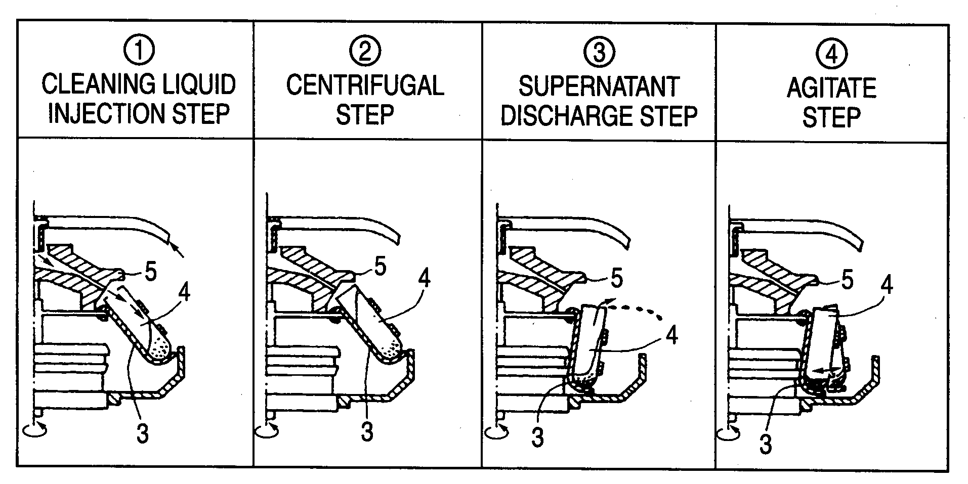
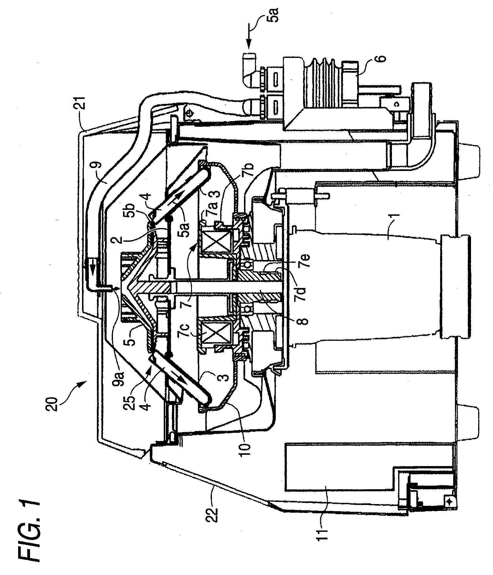
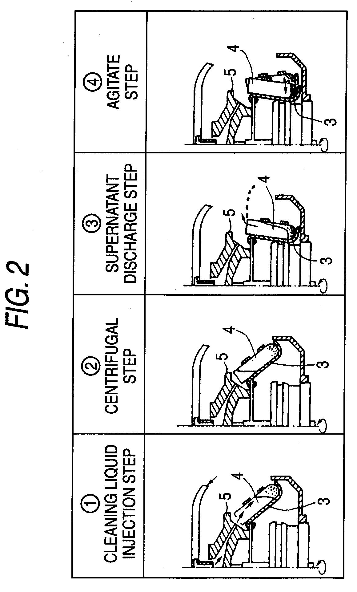
[0052]FIG. 1 is a sectional view showing the entire constitution of a bio cell cleaning centrifuge according to the embodiment, FIG. 2 is a sectional view showing an operating state of a test tube holder of the bio cell cleaning centrifuge in each step of a cleaning process, and FIG. 3 is a time chart showing rotation speed of a motor in the bio cell cleaning centrifuge according to the embodiment, a pump operation and timing of energization to a magnetic element.

[0053]As shown in FIG. 1, a bio cell cleaning centri...


PUM

PropertyMeasurementUnit
Speedaaaaaaaaaa

Abstract

According to an aspect of the present invention, there is provided a bio cell cleaning centrifuge including: a motor; a rotor rotated by the motor; holders that are equipped on the rotor and that hold test tubes to be pivotable toward a rotational radial direction of the rotor; a cleaning liquid distributor mounted on the rotor to supply a cleaning liquid to the test tubes; a locking mechanism that locks the holders so that the test tubes are in a vertical state with respect to the rotational radial direction; and a controller that controls the motor and the locking mechanism, wherein the holders are configured to hold the test tubes so that central axes thereof are inclined from a rotational axis direction toward a rotational tangent direction of the rotor.

Description

CROSS-REFERENCE TO RELATED APPLICATIONS[0001]This application is based upon and claims a priority from prior Japanese Patent Application No. 2007-163559 filed on Jun. 21, 2007, the entire contents of which are incorporated herein by reference.BACKGROUND OF THE INVENTION[0002]1. Field of the Invention[0003]An aspect of the present invention relates to a bio cell cleaning centrifuge for cleaning bio cell such as red blood cell by centrifugal force, and particularly to a bio cell cleaning centrifuge which is suited to make a cleaning advantage large and make cleaning reliability high, and a bio cell cleaning rotor used in the same.[0004]2. Description of the Related Art[0005]Conventionally, a bio cell cleaning centrifuge (blood cell cleaning centrifuge) has been known, which is used, in an antiglobulin test in blood transfusion, a cross-matching test and irregular antibody screening, in order to remove unwanted antibody from a suspension by cleaning red blood cell with a cleaning liqui...

Claims


Application Information

Patent Timeline
IPC IPC(8): B04B9/10B04B11/00B04B13/00
CPCB04B5/0421B04B9/10B04B15/06B04B15/12
Inventor YAMADA, KENJI
Owner HITACHI KOKI CO LTD
Why Eureka
Try Eureka