Flexible mount for a fan and like devices

Inactive Publication Date: 2008-12-25
RICHCO
View PDF0 Cites 1 Cited by
  • Summary
  • Abstract
  • Description
  • Claims
  • Application Information

AI Technical Summary

Benefits of technology

[0004]Preferably, a mounting device embodying the present invention comprises a resilient stud, preferably fabricated from silicone rubber or the like, which is of a durometer permitting it to be extended or stretched for entry into apertures on a frame and chassis. The stud has a number of axially arranged enlarged undulations or ribs which can be drawn into the apertures when the mounting device is stretched and when relaxed can effectively hold the fan or the like in place.
[0005]Mounts for fans and similar devices must meet critical acoustic and vibration standards. These mounts must be used in such a way that no adverse vibration is caused to the fan or the like and its mounting panels, and the flexible mount embodying the present invention meets such standard and does not cause unwelcome vibration or sound problems. The mount embodying the present invention also comprises electrical insulating material, so that undesirable shorting between the mount and its housing is not possible.
[0006]In an alternative embodiment of the invention, the novel mounting device embodying the invention has a break-away end and a medial portion with an enlarged section having a diameter greater than the chassis aperture into which it is inserted, which permits the end adjacent to its panel to be broken away from the stud to provide a neat end for the installation after the fan frame or similar member has been secured to the chassis. This arrangement also provides a spacer between he chassis and the frame or housing for resiliently and securely mounting the fan or other device on the chassis.

Problems solved by technology

However the frame and chassis vary within limited dimensions from manufacturer to manufacture, and a variety of sizes is usually required for installation.
Additionally, in installations where the device is subject to vibration or is mounted on movable equipment, rigid mounting of the device on the chassis can result in making the fan or other device inoperable or causing it to short, particularly if the mount is fabricated from conductive material, such as metal.
Further, conventional devices require time and effort to assemble, since many comprises two pieces which must be connected during installation, and that requires extra effort and cost in assembling such devices on a chassis, as well as a the necessity of maintaining a variety of parts and parts inventory.

Method used


Image

  • Flexible mount for a fan and like devices
  • Flexible mount for a fan and like devices
  • Flexible mount for a fan and like devices

Examples


Embodiment Construction

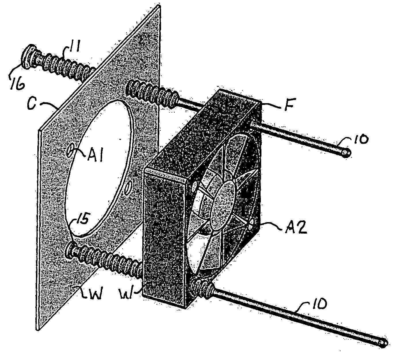
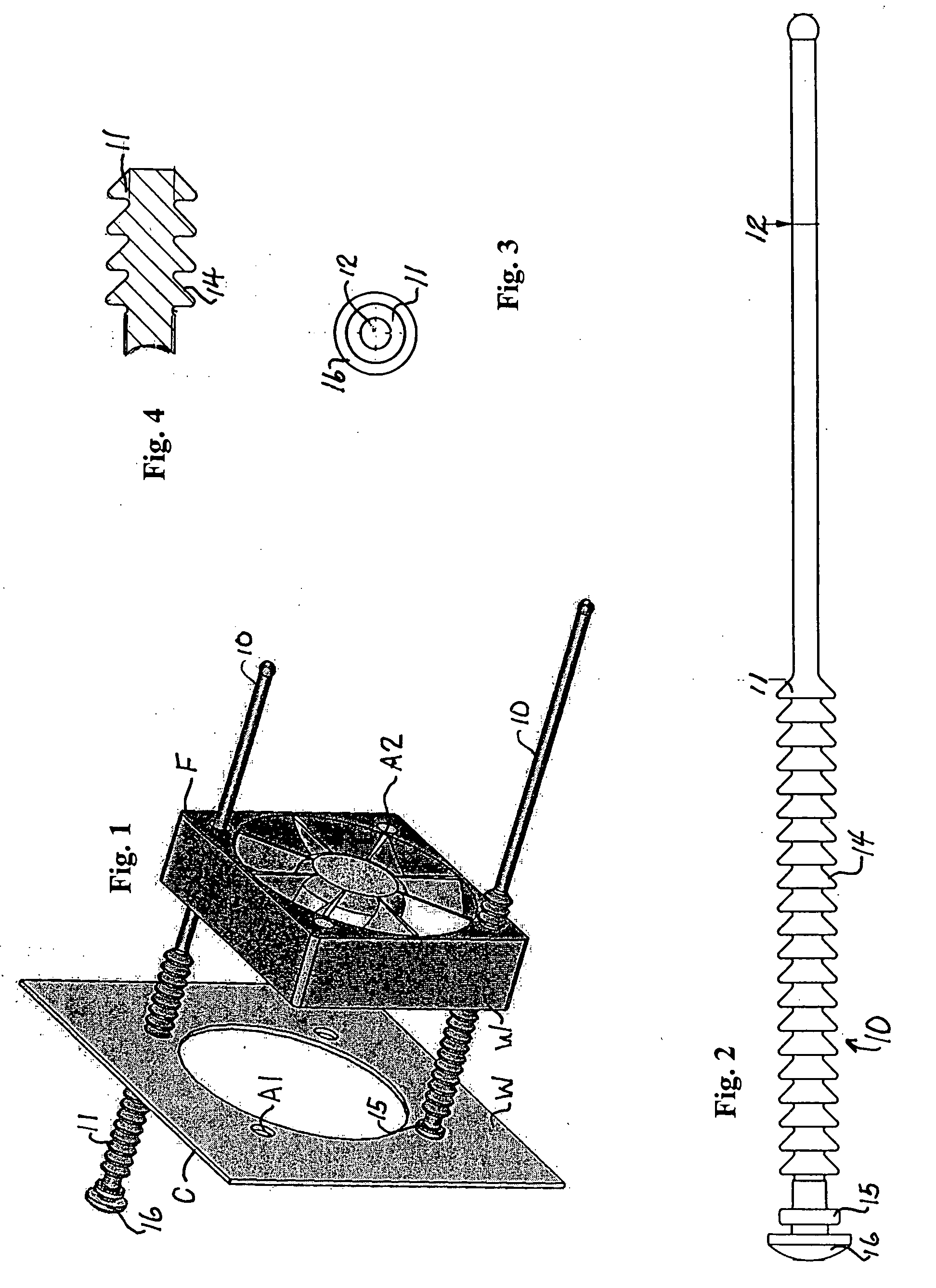
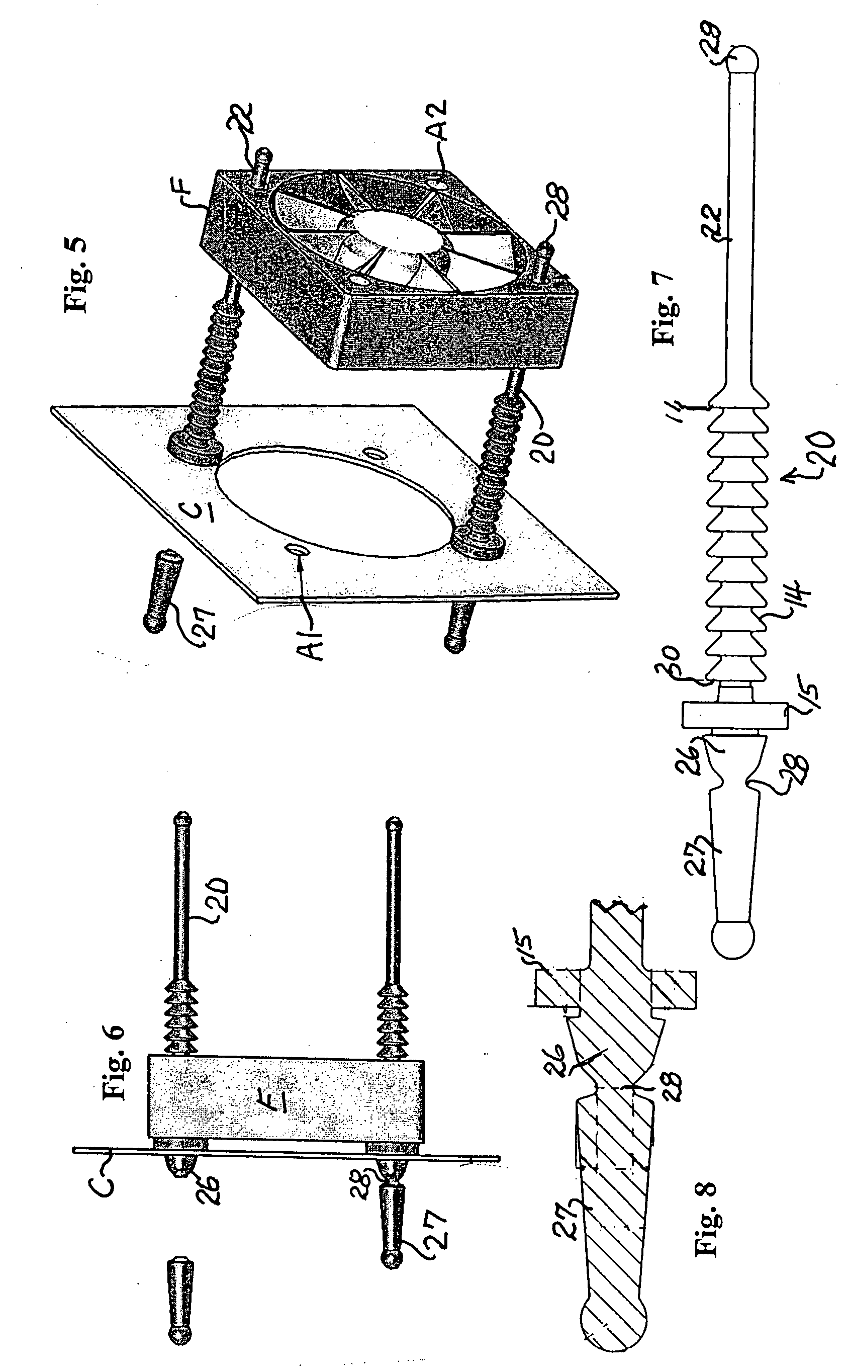
[0027]With reference to FIGS. 1-4, a typical frame F is attached to a chassis or panel C by means of a mounting device 10 embodying the present invention. The frame F and the panel C have corresponding apertures A1 and A2 for receiving the mounting device 10. The frame F may contain a fan B which is subject to vibration and requires a resilient mounting system.

[0028]The mounting device 10 is preferably molded from silicone rubber and is longitudinally stretchable. This mounting device 10 is preferably formed with a series of enlarged axial spaced undulations 11 having a diameter greater than the apertures A1 and A2 of the frame F and chassis C, and a shaft 12 of the mounting device 10 is substantially the diameter of these apertures A1 and A2. The forward face 14 of these undulations 11 is preferably tapered toward the shaft 12, and the mounting device 10 is stretchable sufficiently to permit the undulations when stretched to pass through the apertures A1 and A2, but when relaxed to...


PUM


Abstract

A flexible and stretchable mounting device for a fan or the like which has a shaft, a series of enlarged undulations axially arranged at one end of the shaft, and a head at one end of the shaft, the mounting device being adapted when stretched for insertion into aligned apertures on a chassis and a frame and relaxed to permit a selected undulation to hold the frame in spaced relation to the chassis. The device also includes a break away grip secured to the head for guiding the device into the apertures when stretched and which can be severed from the head when the device is arranged mounted on the chassis and frame.

Description

BACKGROUND AND SUMMARY OF THE INVENTION[0001]This invention relates to a versatile flexible fan mount for mounting a fan or other device on a chassis, and more particularly, for example, to such a mount for electronic and other equipment where a fan is used to ventilate a heat producing structure, such as a computer or the like.[0002]Conventionally, such a device may be mounted by means of bolts or other fasteners for connecting a frame to a panel or chassis to which it must be connected. However the frame and chassis vary within limited dimensions from manufacturer to manufacture, and a variety of sizes is usually required for installation. Additionally, in installations where the device is subject to vibration or is mounted on movable equipment, rigid mounting of the device on the chassis can result in making the fan or other device inoperable or causing it to short, particularly if the mount is fabricated from conductive material, such as metal. Further, conventional devices requ...

Claims


Application Information

Patent Timeline
IPC IPC(8): F04D29/60
CPCF04D25/0613F04D29/668
Inventor REISEL, ROBERTCOURTNEY, TONY
Owner RICHCO
Why Eureka
Try Eureka