
System and Method for Improved Bus Communication

Active Publication Date: 2008-12-11
TWITTER INC
View PDF10 Cites 6 Cited by
  • Summary
  • Abstract
  • Description
  • Claims
  • Application Information

AI Technical Summary

Benefits of technology

[0010]It is a further aspect of the present invention to provide for an improved virtual SES device.
[0011]It is a further aspect of the present invention to provide for an improved virtual SES method.
[0012]It is a further aspect of the present invention to provide for an improved bus communication method.
[0013]It is a further aspect of the present invention to provide for an improved bus communication system.
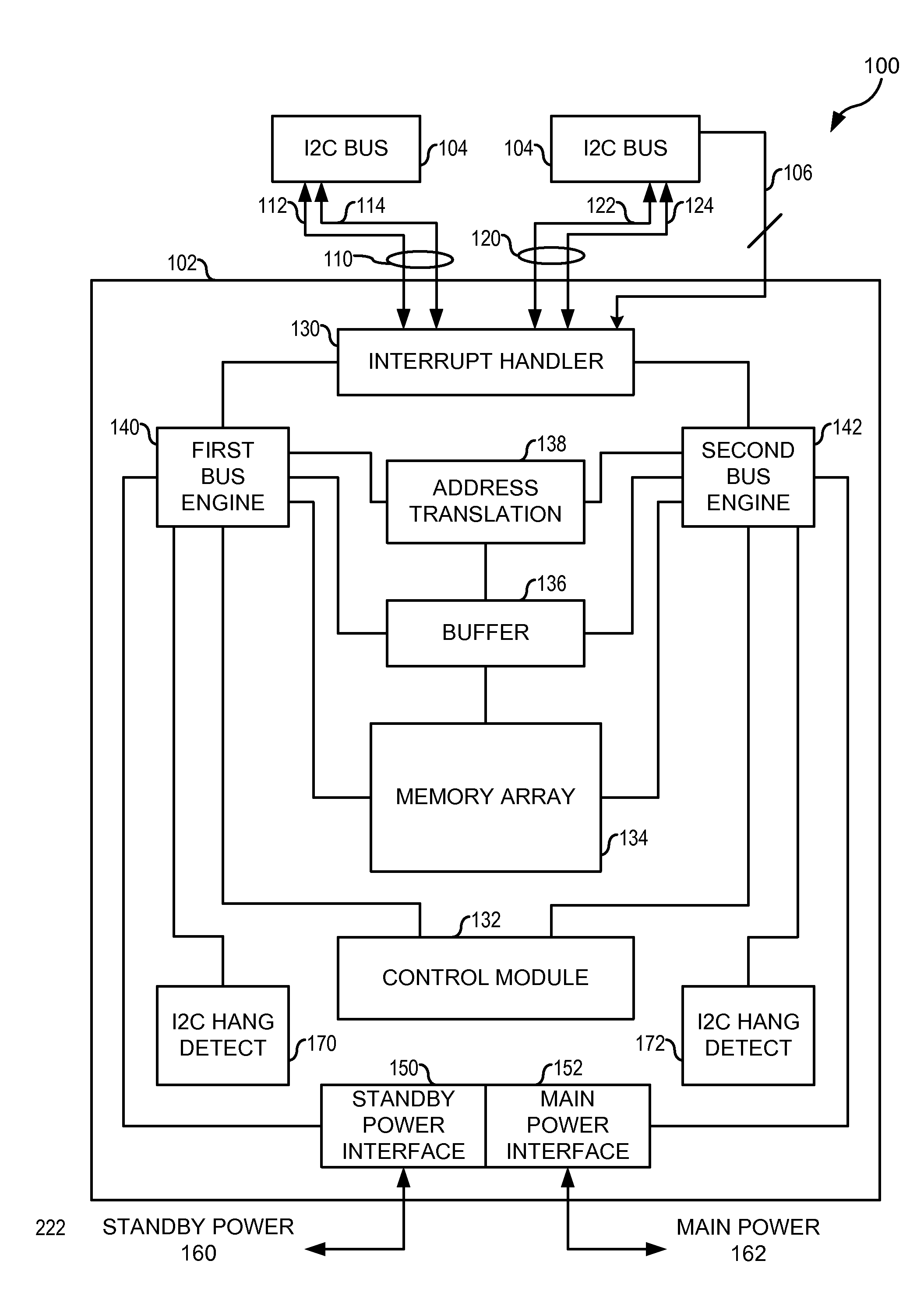
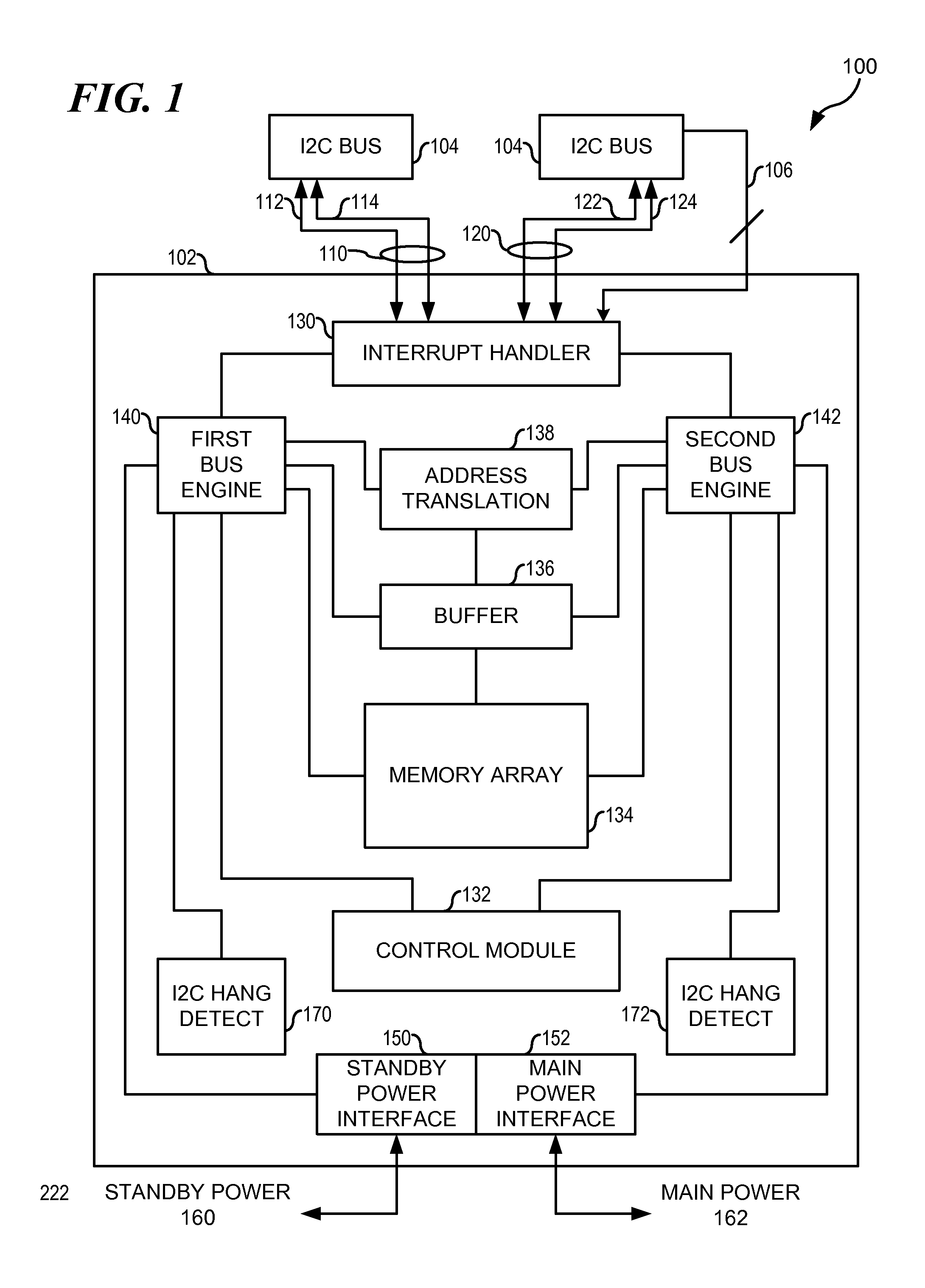
[0014]The aforementioned aspects and other objectives and advantages can now be achieved as described herein. A system for bus communication includes a first port coupled to a bus, comprising a first engine configured to respond to bus signals on the bus, according to a predetermined protocol. A second port couples to the bus, comprising a second engine configured to respond to bus signals according to the predete

Problems solved by technology

This dynamic power up / power down timing frequently causes the I2C ports to stall or “hang up,” a costly and difficult to predict failure condition.
Some attempted solutions exist, but the current solutions offered to address this problem suffer from disadvantages.
This approach, however, typically requires two separate I2C modules with distinct I2C engines, as current I2C chips do not support multiple power domain operation.
Adding an additional I2C chip increases costs and reduces the circuit board space available to other system components.

Method used


Image

  • System and Method for Improved Bus Communication
  • System and Method for Improved Bus Communication
  • System and Method for Improved Bus Communication

Examples


Embodiment Construction

[0019]The particular values and configurations discussed in these non-limiting examples can be varied and are cited merely to illustrate at least one embodiment and are not intended to limit the scope of the invention.

[0020]In the following discussion, numerous specific details are set forth to provide a thorough understanding of the present invention. Those skilled in the art will appreciate that the present invention may be practiced without such specific details. In other instances, well-known elements have been illustrated in schematic or block diagram form in order not to obscure the present invention in unnecessary detail. Additionally, for the most part, details concerning network communications, electromagnetic signaling techniques, user interface or input / output techniques, and the like, have been omitted inasmuch as such details are not considered necessary to obtain a complete understanding of the present invention, and are considered to be within the understanding of per...


PUM


Abstract

A system for bus communication includes a first port coupled to a bus, comprising a first engine configured to respond to bus signals on the bus, according to a predetermined protocol. A second port couples to the bus, comprising a second engine configured to respond to bus signals according to the predetermined protocol. A control module couples to the second port and is configured to receive a port state signal, and to disable the second port based on the received port state signal.

Description

TECHNICAL FIELD[0001]The present invention relates generally to the field of attached computer devices and, more particularly, to a system and method for improved virtual SCSI enclosure services (VSES).BACKGROUND OF THE INVENTION[0002]Modern electronic devices, such as computers, often attach peripheral devices to a primary or main computing system in a standardized protocol. For example, many computing systems couple peripheral devices, such as hard disk drives, to the system using the well-known Small Computer System Interface (SCSI) protocol.[0003]In some systems, an enclosure houses one or more peripheral devices in a protective case or rack that often includes intelligent services. For example, some enclosures can operate to monitor temperature, cooling, power, component identification, and other useful device characteristics. SCSI Enclosure Services (SES) is one protocol that supports tracking these non-data characteristics of peripheral devices.[0004]In some SES systems, call...

Claims


Application Information

Patent Timeline
IPC IPC(8): G06F13/20
CPCG06F13/387Y02B60/1235Y02B60/1228G06F13/4291Y02D10/00
Inventor NADERI, KAVEHBUCKLAND, PATRICK ALLENMOORE, JASON ERICZUZUARREGUI, ABEL ENRIQUE
Owner TWITTER INC
Learn More