
Calibration pattern and duty-cycle distortion correction for clock data recovery in a multi-wire, multi-phase interface

Active Publication Date: 2019-06-25
QUALCOMM INC
View PDF27 Cites 6 Cited by
  • Summary
  • Abstract
  • Description
  • Claims
  • Application Information

AI Technical Summary

Benefits of technology

The patent provides systems, methods, and apparatus for improving communication on a multi-wire and / or multiphase communications link, particularly in devices with multiple IC devices. The patent describes a calibration method for a 3-line interface that involves generating and transmitting a calibration pattern on the interface, consisting of conferling two of three interface lines from one voltage level to another voltage level over a predetermined time interval while maintaining a remaining third interface line at a common mode voltage level. This pattern is received by a calibration data determination circuitry in the receiver, which derives calibration data based on the transmitted pattern. The technical effect of this patent is to improve the quality and reliability of data communication on multi-wire interfaces, particularly in devices with multiple IC devices.

Problems solved by technology

The maximum speed of the C-PHY interface and the ability of a clock and data recovery (CDR) circuit to recover clock information may be limited by the maximum time variation related to transitions of signals transmitted on the different wires of the communication link.

Method used


Image

  • Calibration pattern and duty-cycle distortion correction for clock data recovery in a multi-wire, multi-phase interface
  • Calibration pattern and duty-cycle distortion correction for clock data recovery in a multi-wire, multi-phase interface
  • Calibration pattern and duty-cycle distortion correction for clock data recovery in a multi-wire, multi-phase interface

Examples


Embodiment Construction

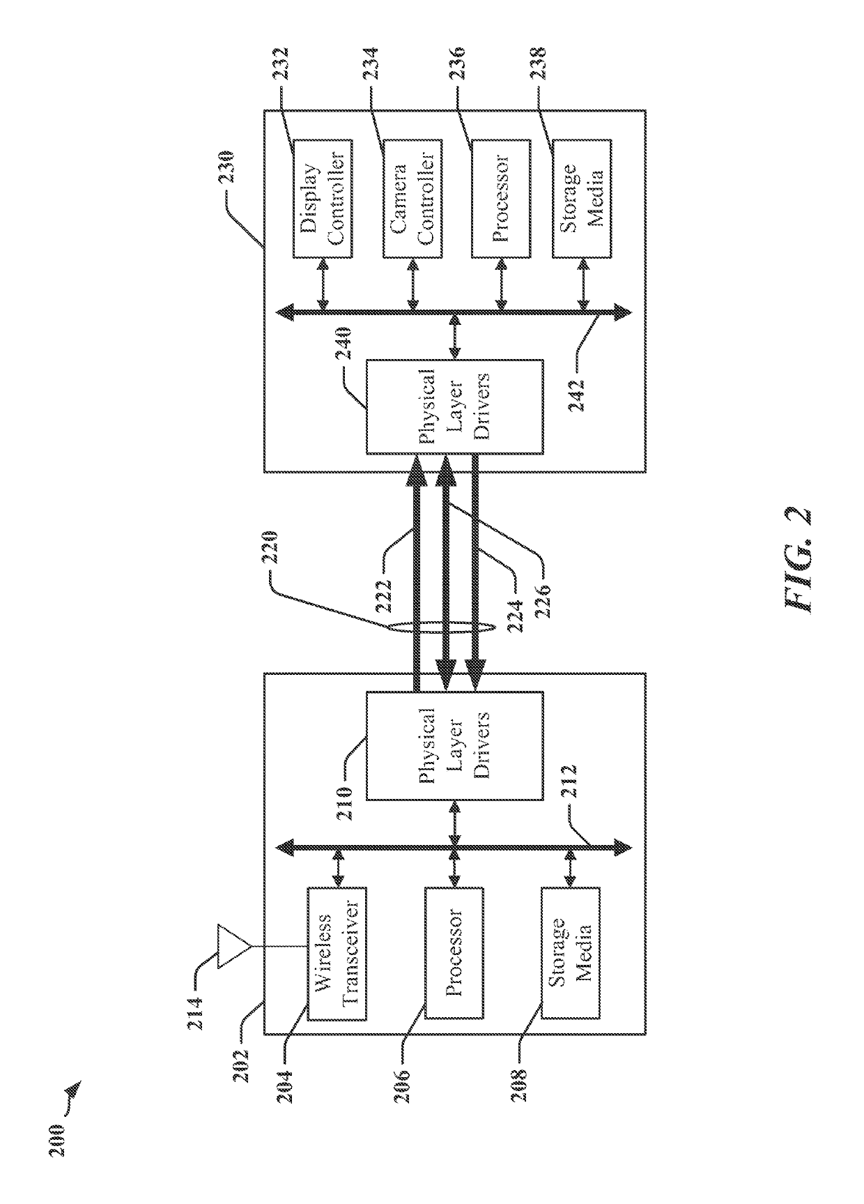
[0029]The detailed description set forth below in connection with the appended drawings is intended as a description of various configurations and is not intended to represent the only configurations in which the concepts described herein may be practiced. The detailed description includes specific details for the purpose of providing a thorough understanding of various concepts. However, it will be apparent to those skilled in the art that these concepts may be practiced without these specific details. In some instances, well-known structures and components are shown in block diagram form in order to avoid obscuring such concepts.

[0030]As used in this application, the terms “component,”“module,”“system” and the like are intended to include a computer-related entity, such as, but not limited to hardware, firmware, a combination of hardware and software, software, or software in execution. For example, a component may be, but is not limited to being, a process running on a processor,...


PUM


Abstract

Methods, apparatus, and systems for calibration and correction of data communications over a multi-wire, multi-phase interface are disclosed. In particular, calibration is provided for data communication devices coupled to a 3-line interface. The calibration includes generating and transmitting a calibration pattern on the 3-line interface, where the generation of the pattern includes toggling two of three interface lines from one voltage level to another voltage level over a predetermined time interval. Furthermore, the generation of the pattern includes maintaining a remaining third interface line at a common mode voltage level over the predetermined time interval, wherein only a single transition occurs for the predetermined time interval. Calibration data may then be derived in a receiver device using the transmitted calibration pattern.

Description

TECHNICAL FIELD[0001]The present disclosure relates generally to high-speed data communications interfaces, and more particularly, to clock generation in a receiver coupled to a multi-wire, multi-phase data communication link.INTRODUCTION[0002]Manufacturers of mobile devices, such as cellular phones, may obtain components of the mobile devices from various sources, including different manufacturers. For example, an application processor in a cellular phone may be obtained from one manufacturer, while an imaging device or camera may be obtained from another manufacturer, and a display may be obtained from yet another manufacturer. The application processor, the imaging device, the display controller, or other types of device may be interconnected using a standards-based or proprietary physical interface. In one example, an imaging device may be connected using the Camera Serial Interface (CSI) defined by the Mobile Industry Processor Interface (MIPI) Alliance. In another example, a d...

Claims


Application Information

Patent Timeline
IPC IPC(8): H04L7/033H04L7/00G09G5/00H04L25/49
CPCH04L7/0041H04L7/033G09G5/008H04L25/49H04L7/0091H04L7/0037G06F13/4278H04L7/0276H04L7/0334H04L25/0276H04L25/4923Y02D10/00G06F13/40
Inventor DUAN, YINGDIXIT, ABHAYCHOU, SHIH-WEILEE, CHULKYU
Owner QUALCOMM INC
Learn More