
Electronic date calculator

a date calculator and electronic technology, applied in computing, instruments, horology, etc., can solve the problems of inconvenient and slow functions, and achieve the effect of convenient calculation and display

Inactive Publication Date: 2008-12-04
PATTON JR ROY CHILSON
View PDF17 Cites 3 Cited by
  • Summary
  • Abstract
  • Description
  • Claims
  • Application Information

AI Technical Summary

Benefits of technology

[0005]These and other shortcomings of the prior art are addressed by the present invention, which provides a date calculator that provides convenient calculation and display of future and past dates.

Problems solved by technology

Normally, determination of the future date would involve laborious manual counting of days and / or reference to several pages of a calendar.
These functions are thus slow and inconvenient.

Method used


Image

  • Electronic date calculator
  • Electronic date calculator
  • Electronic date calculator

Examples


Embodiment Construction

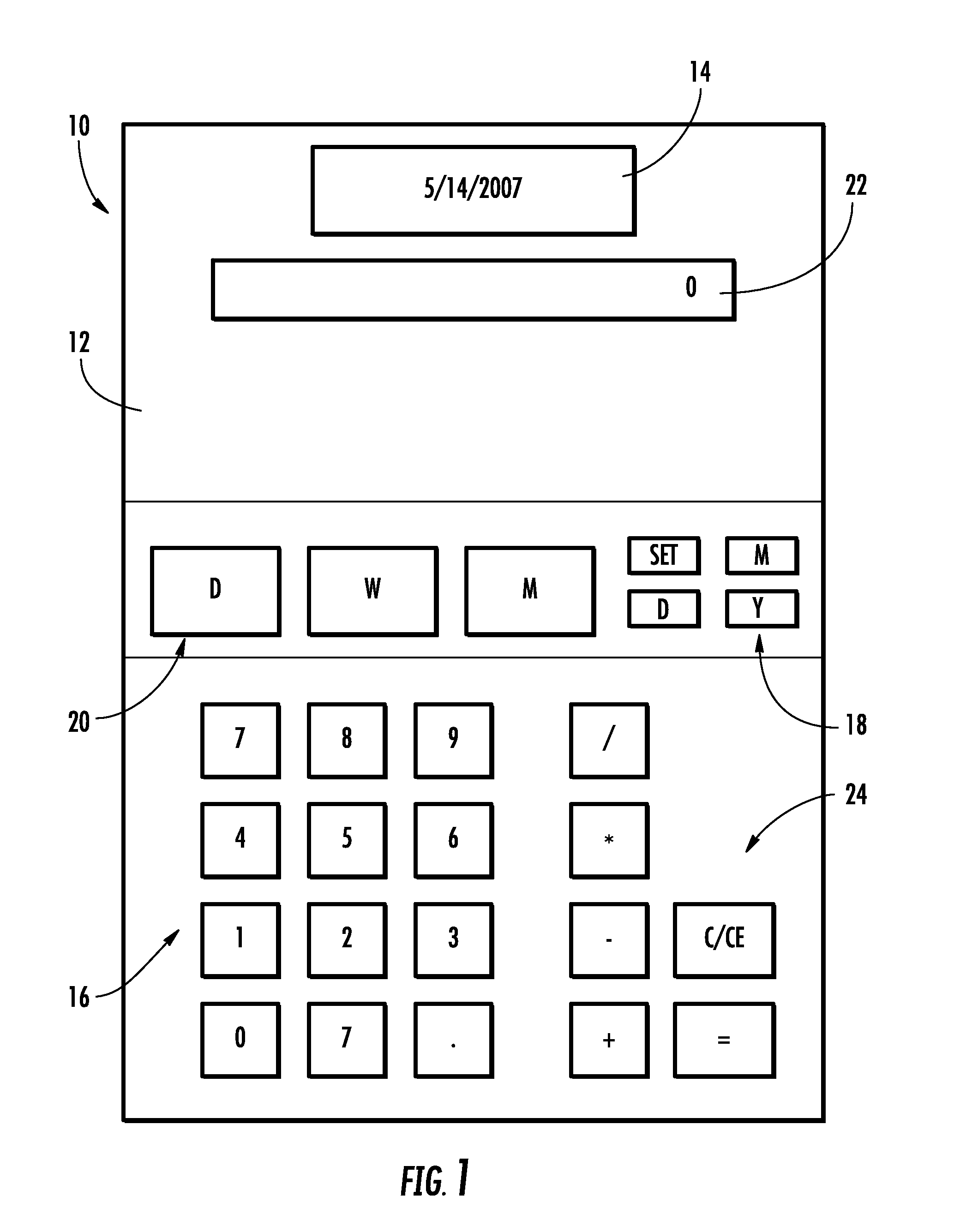
[0017]Referring to the drawings wherein identical reference numerals denote the same elements throughout the various views, FIG. 1 depicts an exemplary date calculator 10 constructed according to an aspect of the present invention. It is similar in construction to a prior art hand calculator and includes a housing 12, a date display 14, numeric keys 16, date setting keys 18, and date function keys 20. In the illustrated example there are three date function keys 20 which are labeled “D” for days, “W” for weeks, and “M” for months, respectively.

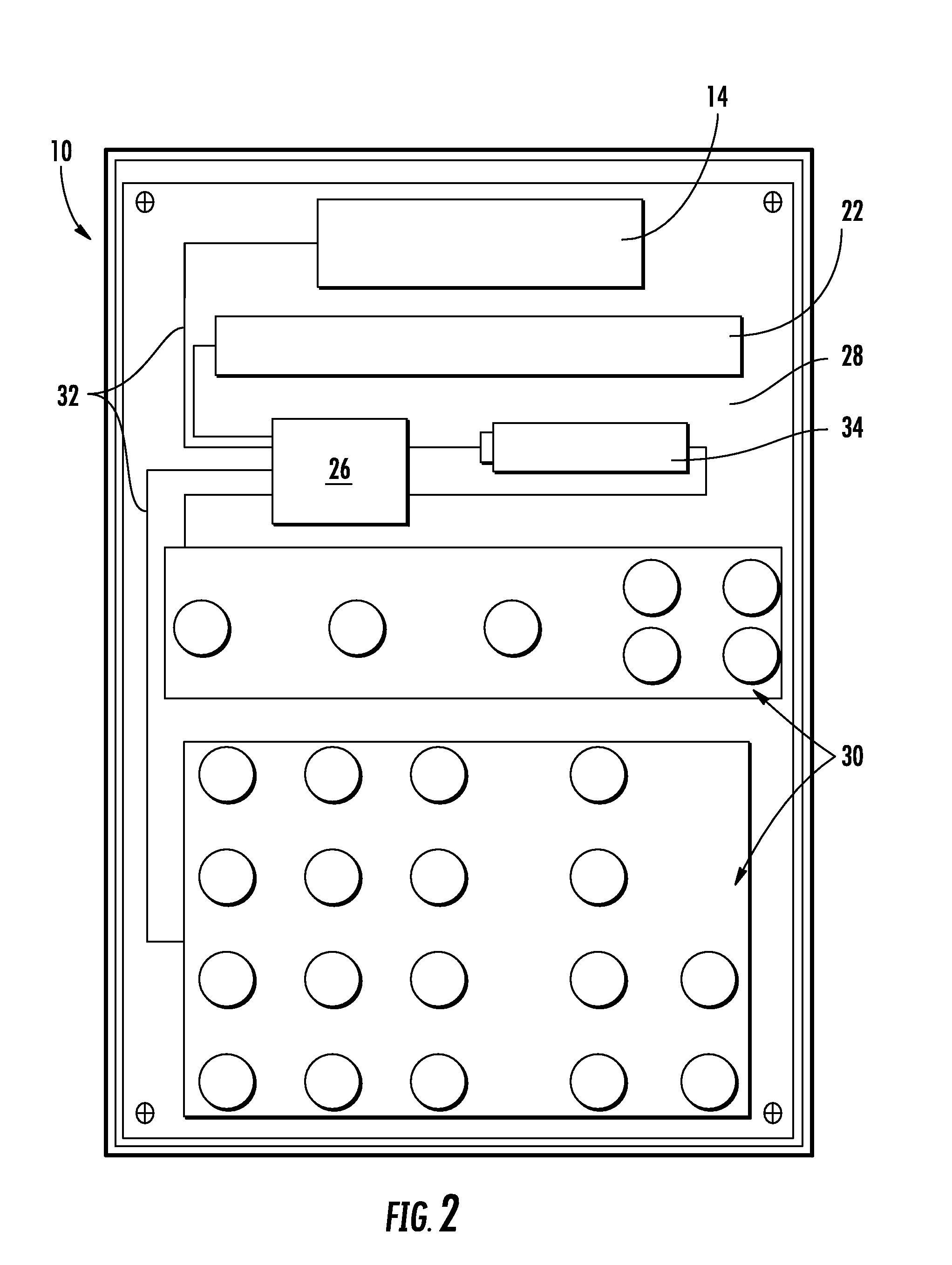
[0018]As shown here, the date calculator 10 also incorporates the functions of a conventional mathematical calculator and includes a numeric display 22 and mathematical function keys 24 used to enter arguments and commands and to display results of mathematical operations. The principle of the present invention may be incorporated in any type of electronic device that has a date display including, for example, watches or alarm clocks, hand or ...


PUM


Abstract

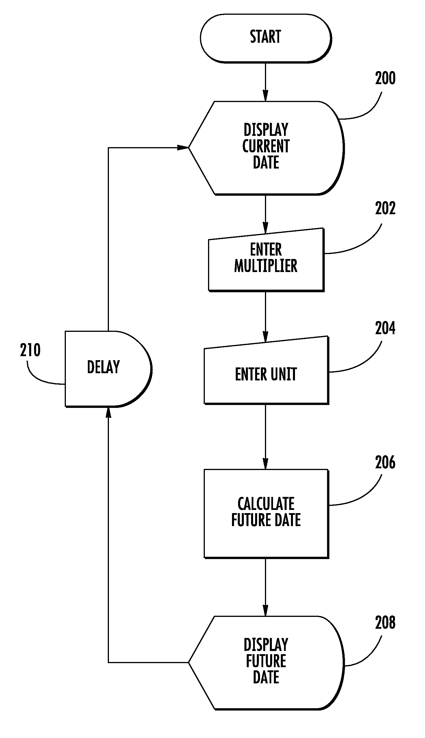
An electronic date calculator includes an electronic processor, input keys operably connected to the processor, at least one date function key corresponding with a selected date unit and operably connected to the processor, and a display operably connected to the processor. The processor is programmed to drive the display to show a present date. In response solely to entry of a multiplier from the input keys and a date unit from the date function key, the processor adds a product of the selected date unit and the multiplier to the present date to generate a resulting date, and drives the first display to show the resulting date.

Description

CROSS-REFERENCE TO RELATED APPLICATIONS[0001]This application claims the benefit of Provisional Application No. 60 / 940,512 Filed May 29, 2007.BACKGROUND OF THE INVENTION[0002]This invention relates generally to electronic calendars and more particularly to an electronic calendar with date calculation functions.[0003]Various types of electronic calendars and timepieces are known which can track and display the present date. Calculators and computers are also available which can display the present date, and can perform calculations using dates.[0004]In various situations it is desirable to know the exact value of a date which is a certain interval in the future or the past, i.e. a certain number of days, weeks, or months ahead of or prior to the present time. For example, it may be desired to schedule a business meeting, medical appointment, bill payment, business action item, or the like to occur 30 days, two weeks, or six months from the present day. Normally, determination of the ...

Claims


Application Information

Patent Timeline
Patent Type & Authority Applications(United States)
IPC IPC(8): G06F19/00
CPCG06F15/16
Inventor PATTON, JR., ROY CHILSON
Owner PATTON JR ROY CHILSON
Learn More