
Leadless Implantable Cardioverter Defibrillator

a cardioverter and implantable technology, applied in the field of cardioverter defibrillators, can solve the problems of insufficient blood pumping to sustain life, hampered technology, and prone to acute risk of cardiac tamponade in technology

Inactive Publication Date: 2008-11-27
UNIVERSITY OF ROCHESTER
View PDF73 Cites 124 Cited by
  • Summary
  • Abstract
  • Description
  • Claims
  • Application Information

AI Technical Summary

Benefits of technology

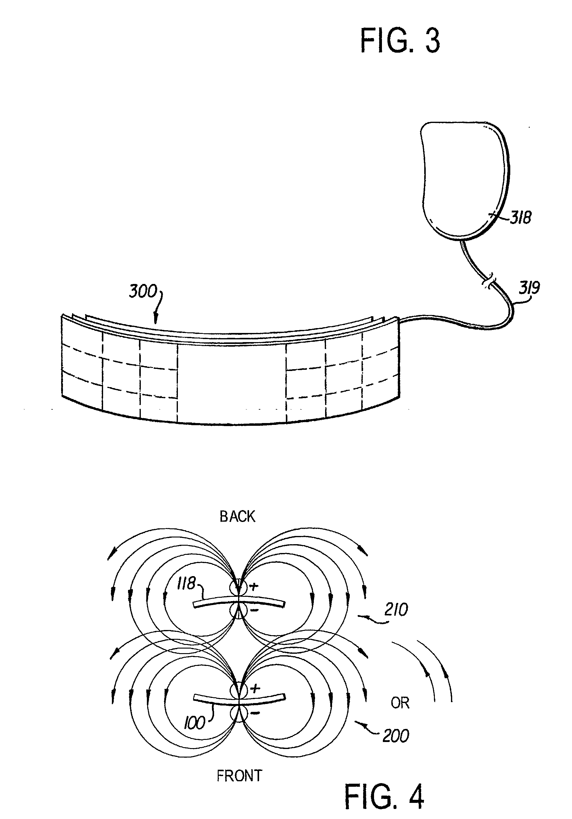
[0007]In another approach, one of the remote sensors described above is replaced with a micro-thin patch with a lead connection to the ICD for a + / −polarity reversal implant. In yet another approach, ultrasonic signals are used to stimulate the heart as a back-up or as an adjunct to the electrical pacing that is provided. The ultrasonic signals could be used as an emergency pacing back-up. Antennae / transducers are located on the patient side of the device and include adjustable projection angles to provide the best acoustic angle.

Problems solved by technology

Fibrillation is a condition where the heart has very rapid shallow contractions and, in the case of ventricular fibrillation, may not pump a sufficient amount of blood to sustain life.
However, these technologies are hampered by the use of a transvenous lead for electrophysiologic stimulation.
Those technologies are susceptible to an acute risk of cardiac tamponade, perforation of the heart or vasculature and long term risk of endocarditis or a need for intracardiac extraction of the lead due to failure.
Also, current technologies present a problem for intracardiac defibrillation implantation in younger patients or in patients who are not candidates for the implantation because of anatomical abnormalities.
Complex steps and risks are involved in obtaining venous vascular access and placement of the transvenous lead in the patient population requiring the defibrillation.

Method used


Image

  • Leadless Implantable Cardioverter Defibrillator
  • Leadless Implantable Cardioverter Defibrillator
  • Leadless Implantable Cardioverter Defibrillator

Examples


Embodiment Construction

[0015]In describing a preferred embodiment of the invention illustrated in the drawings, certain specific terminology will be used for the sake of clarity. However, the invention is not intended to be limited to that specific terminology, and it is to be understood that the terminology includes all technical equivalents that operate in a similar manner to accomplish the same or similar result.

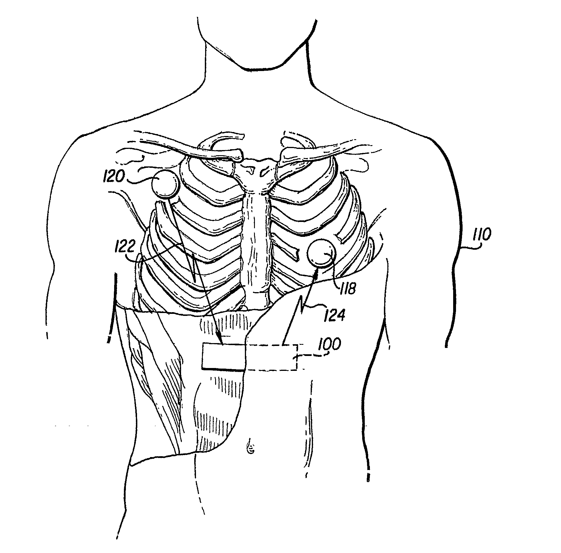
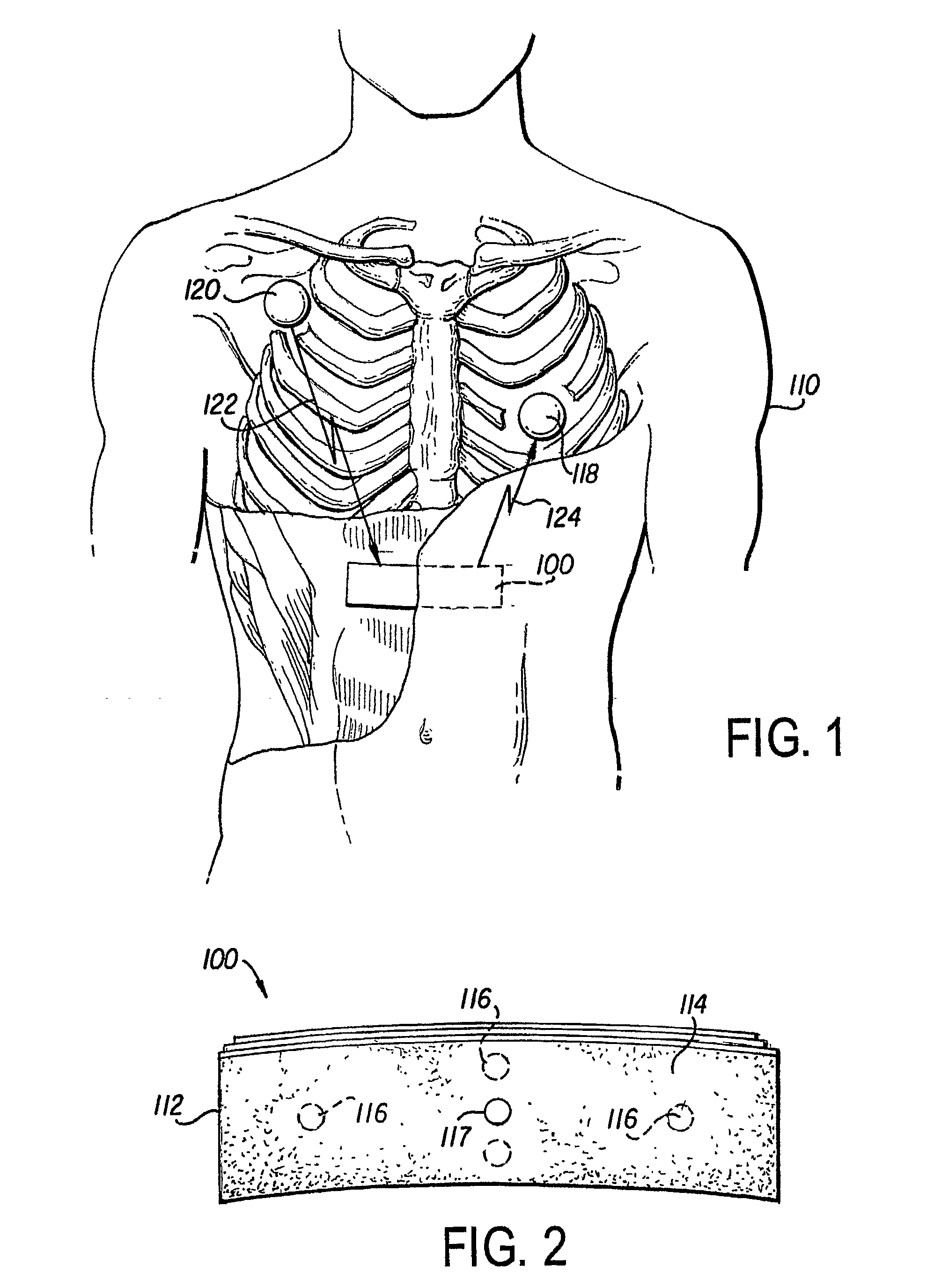
[0016]FIG. 1 shows a preferred embodiment of the implantable cardioverter defibrillator (ICD) 5. The defibrillator 5 includes a controller 100 and one or more satellite sensors 118, 120. The controller 100 is surgically implanted in the subcutaneous tissue in proximity to the chest and abdomen of a medical patient 110. The purpose of the ICD 5 is to produce an electrical stimulus or shock that either paces the heart or defibrillates the heart and returns the heart to a normal rhythm. The device 5 needs to be in close proximity to the target organ (here, the heart) in order to provide the highes...


PUM


Abstract

A leadless implantable cardioverter defibrillator (5) for treatment of sudden cardiac death includes a controller and at least one remote module. The defibrillator does not require transvenous / vascular access for intracardiac lead placement. The controller is leadless and uses subcutaneous tissue in proximity of the chest and abdomen for both sensing and defibrillation. The controller and one or more remote sensors sense a need for defibrillation and wireless communicate with the controller. The controller and one of the sensors discharge a synchronized defibrillation pulse to the surrounding subcutaneous tissue in proximity to the heart.

Description

RELATED APPLICATIONS[0001]The present application claims priority to provisional application Ser. Nos. 60 / 567,447, 60 / 567,448 and 60 / 567,449, each of which were filed on May 4, 2004.TECHNICAL FIELD[0002]The present invention is generally related to cardiac defibrillators and, more particularly, is related to a method and an apparatus for providing a leadless implantable cardioverter defibrillator for the treatment of sudden cardiac death.BACKGROUND OF THE INVENTION[0003]Defibrillation / cardioversion is a technique employed to counter arrhythmic heart conditions including some tachycardias in the atria and / or ventricles. Fibrillation is a condition where the heart has very rapid shallow contractions and, in the case of ventricular fibrillation, may not pump a sufficient amount of blood to sustain life. A defibrillator often is implanted in the chest cavity of a person who is susceptible to reoccurring episodes of ventricular fibrillation. Typically, electrodes are employed to stimulat...

Claims


Application Information

Patent Timeline
Patent Type & Authority Applications(United States)
IPC IPC(8): A61N1/39A61N1/05A61N1/372A61N1/375
CPCA61N1/05A61N1/372A61N1/37288A61N1/375A61N1/3756A61N1/3956A61N1/37512
Inventor ROSERO, SPENCER
Owner UNIVERSITY OF ROCHESTER
Learn More