Funneled wind turbine aircraft

Inactive Publication Date: 2008-11-27
POTTER LYNN
View PDF15 Cites 21 Cited by
  • Summary
  • Abstract
  • Description
  • Claims
  • Application Information

AI Technical Summary

Benefits of technology

[0009]A wind-to-power generator aircraft comprising: a primary body filled with a lighter-than-air gas to provide buoyancy to the aircraft; a wind funnel coupled along a length of the primary body, a large end of the wind funnel located at a front of the aircraft and a small end of the wind funnel located approximately at a middle of the aircraft, the wind funnel positioned to concentrate airflow from the large end to the small end; a wind-to-electricity turbine coupled at the small end of the wind funnel wherein the turbine is ducted; and a tether coupled to the aircraft at a point near the turbine to secure the aircraft to the ground and transmit electricity from the turbine to a ground station is provided.
[0010]In some embodiments, the turbine may be adapted to convert the airflow into electricity. The aircraft of claim may further include a rudder coupled to the rear of the aircraft. The wind funnel of the aircraft may be coupled along a bottom portion of the primary body. The primary body may be made from a light weight material. The aircraft may further include a winch configured to adjust the altitude of the aircraft and align it with the airflow. The aircraft may further include a buoyancy controller configured to maintain the aircraft at a desired altitude. The aircraft of may further include a plurality of winches located at a front end and a rear end of the aircraft wherein the winches are tied to the tether and adapted to control pitch. The aircraft of may further include a supporting ring about the opening of the wind funnel and a plurality of ribs along the length of the wind funnel. In one embodiment, the primary body has a longitudinal blimp-like shape.
[0011]An aircraft including: a primary body filled with a lighter-than-air gas to provide buoyancy to the aircraft; a wind funnel defined within the primary body along a length of the primary body, a large end of the wind funnel located at a front of the aircraft and a small end of the wind

Problems solved by technology

However, many wind-based energy generating systems (e.g., wind mills, etc.) fail to be cost-efficient.
This design fails to harness or concentrate wind power to efficiently generate electricity.
This design is cumbersome in that the “fan belt” is run from the aircraft to ground.
Consequently, such system may be difficult to implement in high-altitude applications.
Additionally, many prior art wind turbines devices are not optimized to take advantage of high-altitude wind currents which tend to be steadier and more powerful than low-altitude wind currents.

Method used


Image

  • Funneled wind turbine aircraft
  • Funneled wind turbine aircraft
  • Funneled wind turbine aircraft

Examples


Embodiment Construction

[0023]In the following detailed description of the invention, numerous specific details are set forth in order to provide a thorough understanding of the invention. However, the invention may be practiced without these specific details. In other instances well known methods, procedures, and / or components have not been described in detail so as not to unnecessarily obscure aspects of the invention.

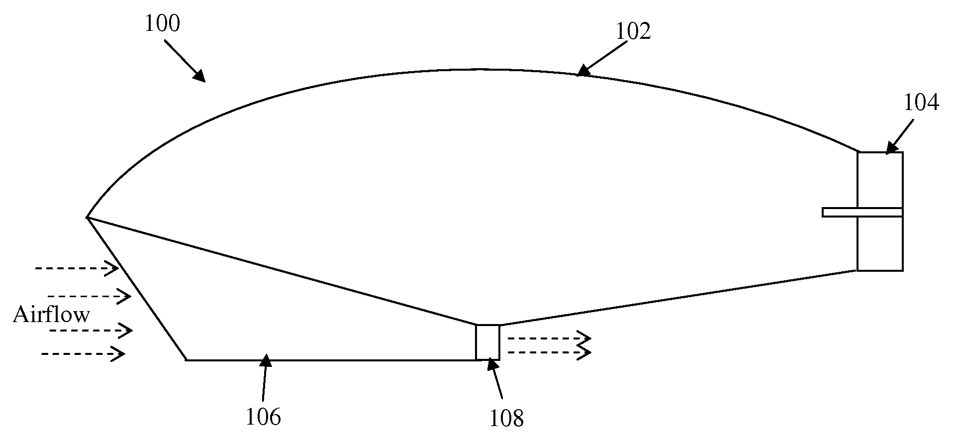
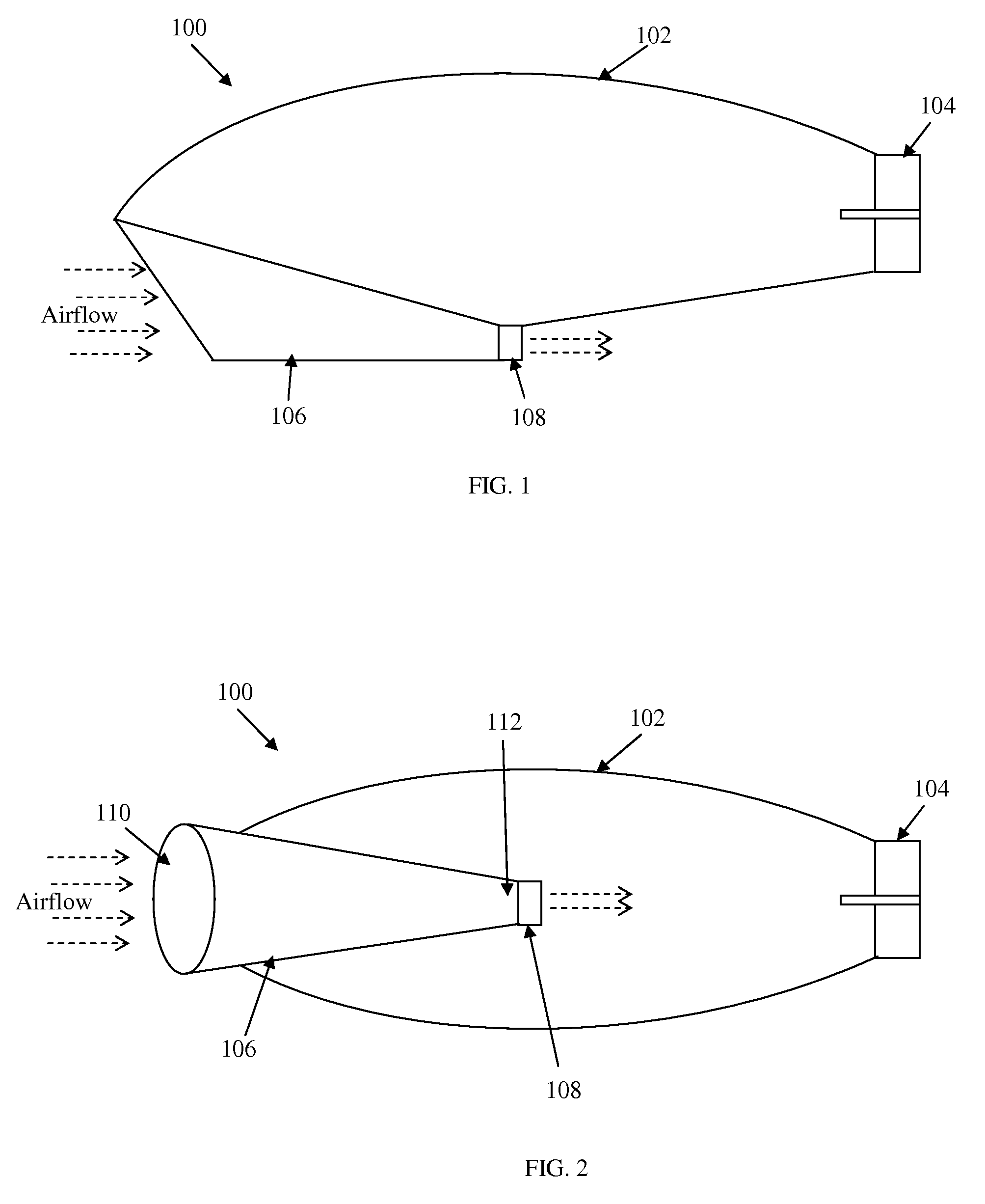
[0024]One aspect of the present invention provides an aircraft adapted to house a wind funnel and a wind turbine configured to convert the airflow through the wind funnel into electricity. An electrical cable between the aircraft and a ground station transfers the generated electricity from the aircraft to the receiving ground station for distribution.

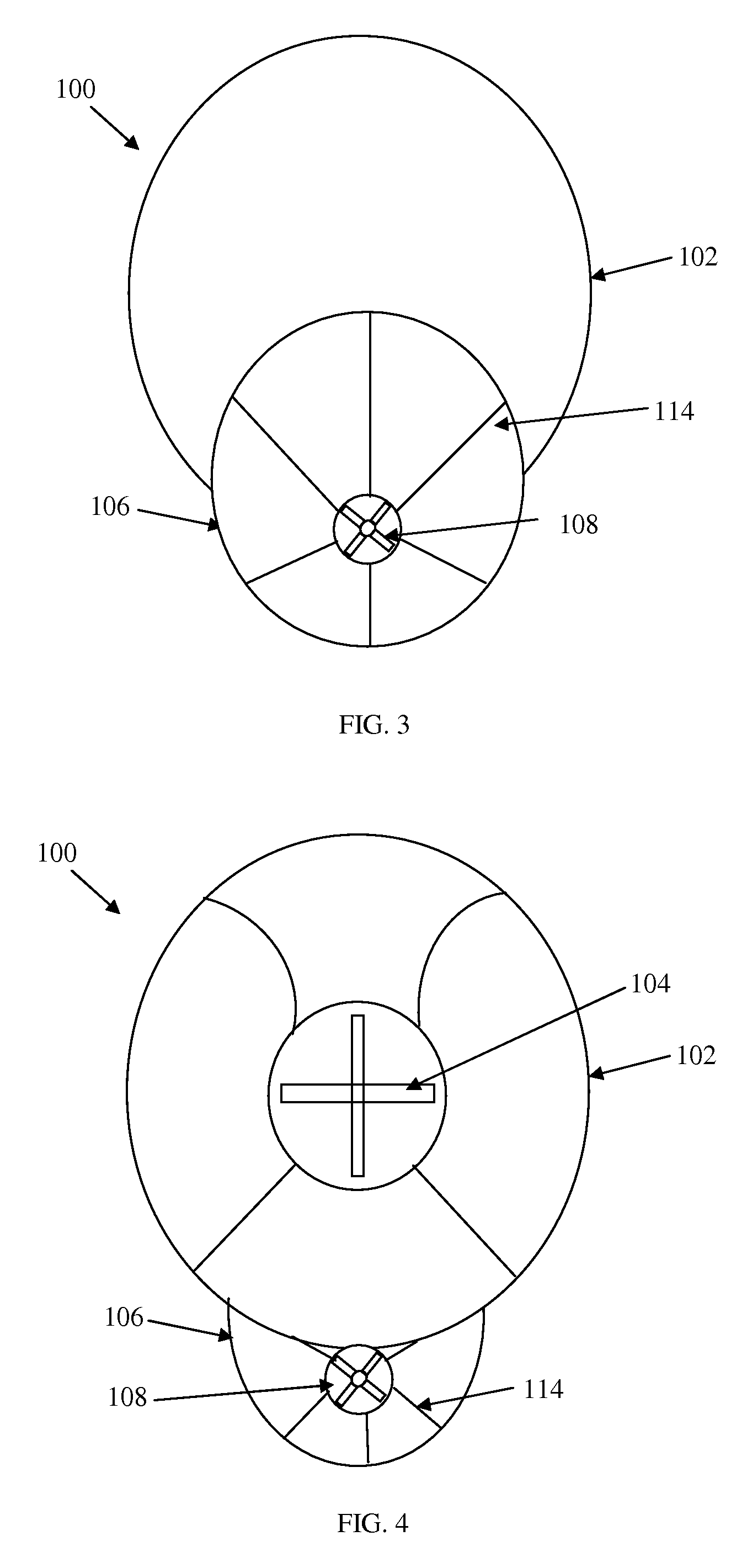
[0025]FIGS. 1, 2, and 3 illustrate different views of an aircraft 100 (e.g., blimp) adapted to house a wind funnel turbine according to one embodiment. FIG. 1 illustrates a side view of an embodiment of an aircraft for converting air to electr...


PUM


Abstract

An aircraft adapted to house a wind funnel and a wind turbine configured to convert the airflow through the wind funnel into electricity. An electrical cable between the aircraft and a ground station transfers the generated electricity from the aircraft to the receiving ground station for distribution. A plurality of aircraft according to certain embodiments may form a system for generating electricity from airflow.

Description

CLAIM OF PRIORITY[0001]This is a non-provisional patent application which claims priority to Provisional Patent Application No. 60 / 939,604 filed May 22, 2007.BACKGROUND OF INVENTION[0002]1. Field[0003]The invention relates to the field of wind-based energy generation and, in particular, to a high-altitude blimp having a funneled wind turbine that improves electricity generation.[0004]2. Background[0005]In recent years, environmentally friendly and cost-efficient energy sources have been explored to reduce dependence on fossil-based fuels. One such alternative energy source is wind-based electric energy. However, many wind-based energy generating systems (e.g., wind mills, etc.) fail to be cost-efficient.[0006]U.S. Pat. No. 7,129,596 describes a hovering wind turbine in which structures with turbine blades are supported in the air by a plurality of blimps. This design fails to harness or concentrate wind power to efficiently generate electricity.[0007]U.S. Pat. No. 4,166,596 describe...

Claims


Application Information

Patent Timeline
IPC IPC(8): F03D1/04F03D11/04
CPCF03D1/04F03D11/04F05B2240/13F05B2240/40F05B2240/922F05B2250/323Y02E10/725Y02E10/728F03D13/20F03D9/32F03D80/00Y02E10/72
Inventor POTTER, LYNN
Owner POTTER LYNN
Why Eureka
Try Eureka