
Actuator control apparatus

a control apparatus and actuator technology, applied in electrical control, valve arrangements, combustion engines, etc., can solve the problems of abnormal diagnosis of variable valve mechanism, inability to properly change the maximum lift of intake valves, so as to improve the accuracy of diagnosis of actuators.

Inactive Publication Date: 2008-11-27
TOYOTA JIDOSHA KK
View PDF0 Cites 21 Cited by
  • Summary
  • Abstract
  • Description
  • Claims
  • Application Information

AI Technical Summary

Benefits of technology

[0013]In view of the above, the invention has been made to provide an actuator control apparatus that improves the accuracy of diagnosis of an actuator.
[0016]According to the actuator control apparatus described above, in a state where the temperature of movable portions of the actuator is significantly lower than the temperature of the engine coolant (e.g., a state from a cold start of the internal combustion engine to the end of the warming-up of the internal combustion engine), the reference time, which is set according to the temperature of the engine coolant, is further extended according to the ambient temperature around the internal combustion engine. This minimizes the possibility of the actuator being erroneously diagnosed to be in an abnormal state when it is actually in a normal state. As a result, the accuracy of the diagnosis of the actuator improves.
[0018]According to the actuator control apparatus described above, upon the diagnosis by the diagnosis portion, the reference amount is calculated as a function using the ambient temperature around the internal combustion engine as a variable such that the lower the ambient temperature, the larger the reference amount. Therefore, even in a state where the temperature of movable portions of the actuator is significantly lower than the temperature of the engine coolant (e.g., a state from a cold start of the internal combustion engine to the end of the warming-up of the internal combustion engine), the actuator is prevented from being erroneously diagnosed to be in an abnormal state when it is actually in a normal state. As a result, the accuracy of the diagnosis of the actuator improves.
[0020]According to the actuator control apparatus described above, in a state where the temperature of movable portions of the actuator is significantly lower than the temperature of the engine coolant (e.g., a state from a cold start of the internal combustion engine to the end of the warming-up of the internal combustion engine), the reference amount, which is set according to the temperature of the engine coolant, is further increased according to the ambient temperature around the internal combustion engine. This minimizes the possibility of the actuator being erroneously diagnosed to be in an abnormal state when it is actually in a normal state. As a result, the accuracy of the diagnosis of the actuator improves.
[0022]According to the actuator control apparatus described above, upon the diagnosis by the diagnosis portion, the reference time is calculated as a function using the ambient temperature around the internal combustion engine as a variable such that the lower the ambient temperature, the longer the reference time. Therefore, even in a state where the temperature of movable portions of the actuator is significantly lower than the temperature of the engine coolant (e.g., a state from a cold start of the internal combustion engine to the end of the warming-up of the internal combustion engine), the actuator is prevented from being erroneously diagnosed to be in an abnormal state when it is actually in a normal state. As a result, the accuracy of the diagnosis of the actuator improves.

Problems solved by technology

When the variable valve mechanism is placed in an abnormal state due to, for example, foreign matter being jammed at movable portions of the variable valve mechanism, degraded oil sticking to the movable portions, and so on, the maximum lift of the intake valves becomes unable to be properly changed in accordance with the operation state of the internal combustion engine.
More specifically, if the deviation of the actual maximum lift from the target maximum lift has continuously been larger than a reference value for a reference time or longer, the state of the variable valve mechanism is diagnosed to be abnormal.
That is, the state of the variable valve mechanism is diagnosed to be abnormal when the variable valve mechanism can not be driven or when the response of the variable valve mechanism is excessively low.
As such, if the variable valve mechanism is diagnosed in the manner as described above even when the response of the variable valve mechanism is temporarily low due to a low temperature, the variable valve mechanism may be erroneously determined to be in an abnormal state.
As a result, the variable valve mechanism is erroneously diagnosed to be in an abnormal state despite that it is actually in a normal state, which is a problem.
As well as in the case where the reference time is changed in accordance with the engine coolant temperature, such a problem may occur also in the case where a reference value for determining the deviation of the actual maximum valve lift from the target maximum valve lift is set such that the lower the engine coolant temperature, the larger the reference value.
Although a variable valve mechanism for changing valve characteristics including the maximum lift of the valves of an internal combustion engine has been described above, it is to be understood that problems identical or similar to the one described above may occur to various other actuator control apparatuses that change an engine state amount by controlling the actual operation position of an actuator to its target operation position set based on the engine operation state.

Method used


Image

  • Actuator control apparatus
  • Actuator control apparatus
  • Actuator control apparatus

Examples


Embodiment Construction

[0034]In the following description and the accompanying drawings, the present invention will be described in greater detail with reference to the example embodiments.

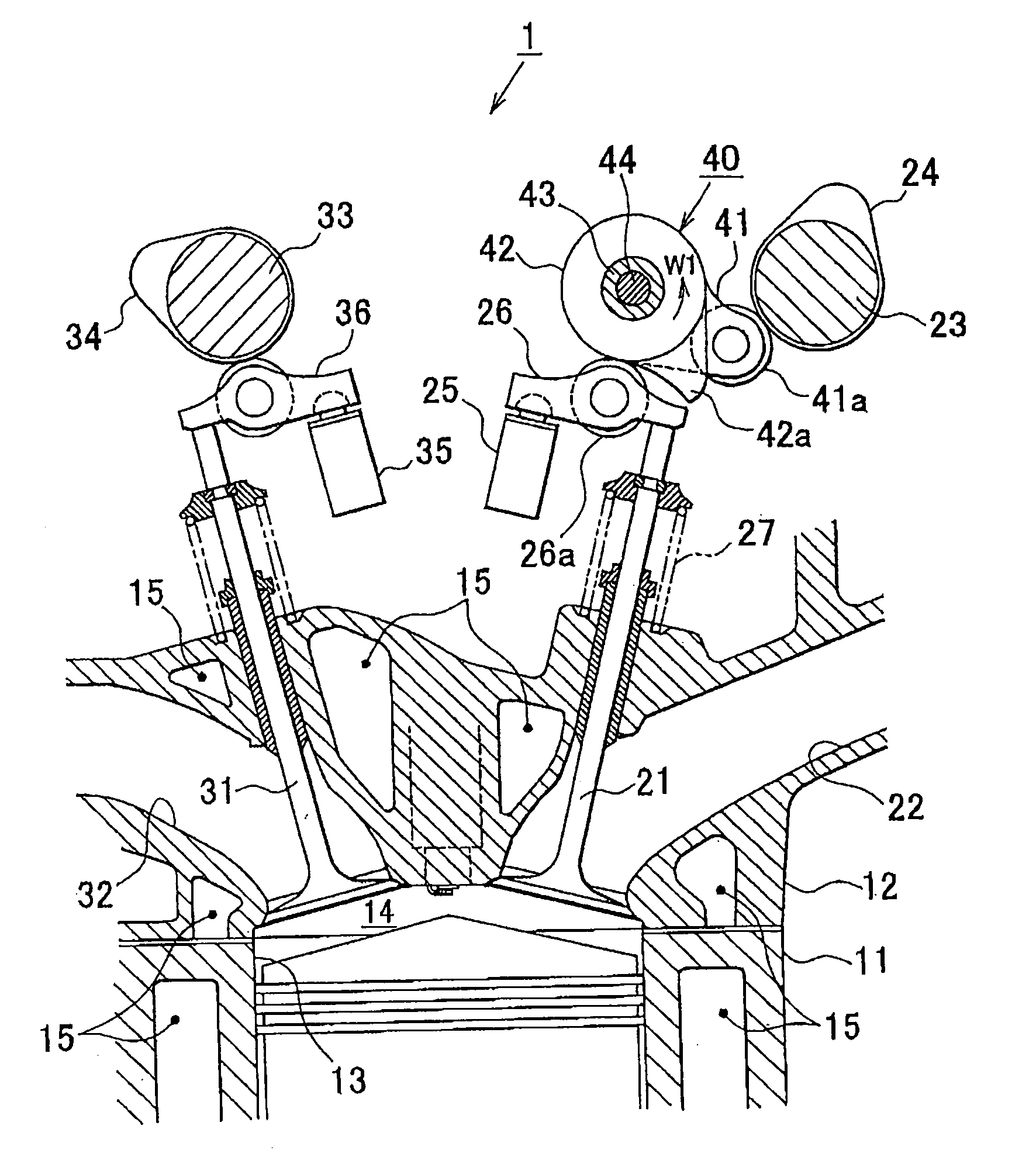
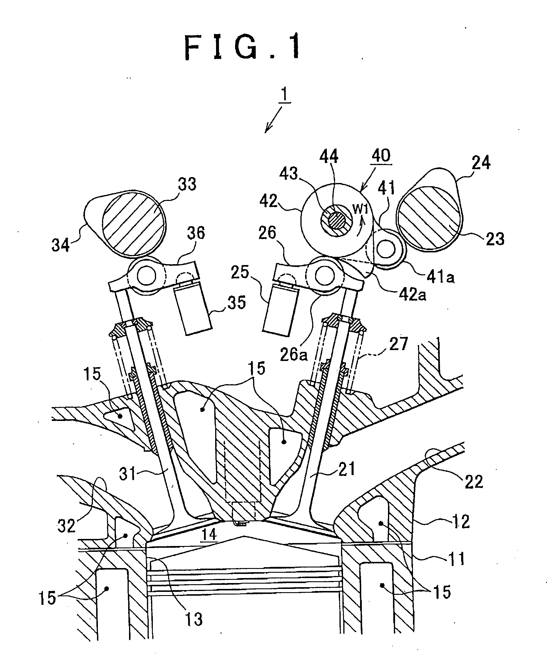
[0035]Hereinafter, with reference to FIG. 1 to FIG. 7, example embodiments of the invention will be described which are applied to a variable valve mechanism operable to change the maximum lift of the intake valves, which is one of state amounts of an internal combustion engine for vehicles. FIG. 1 is a cross-sectional view cutting through a portion of the internal combustion engine.

[0036]Referring to FIG. 1, a plurality of cylinders 13 is formed in a cylinder block 11 of an internal combustion engine 1, and intake ports 22 and exhaust ports 32 are formed in a cylinder head 12 such that they communicate with combustion chambers 14 in the respective cylinders 13, and the cylinder head 12 is mounted on the cylinder block 11. In the cylinder head 12, intake valves 21 for opening and closing the intake ports 22 and exhaust ...


PUM


Abstract

An actuator control apparatus is provided which has: an actuator provided in an internal combustion engine at a position distant from combustion chambers to change an engine state amount; a sensor that detects the actual operation position of the actuator; a controller that controls the actuator to bring the actual operation position to a target operation position set based on the engine operation state; a diagnosis portion that diagnoses the actuator to be in an abnormal state when the deviation of the actual operation position from the target operation position has been larger than a reference amount for a reference time; and a setting portion that sets, upon the diagnosis by the diagnosis portion, the reference time such that the lower the engine coolant temperature, the longer the reference time, and the lower the ambient temperature, the longer the reference time corresponding to the engine coolant temperature.

Description

INCORPORATION BY REFERENCE[0001]The disclosure of Japanese Patent Application No. 2007-138203 filed on May 24, 2007, including the specification, drawings and abstract is incorporated herein by reference in its entirety.BACKGROUND OF THE INVENTION[0002]1. Field of the Invention[0003]The invention relates to an actuator control apparatus having an actuator provided in an internal combustion engine at a position distant from a combustion chamber and operable to change a state amount of the internal combustion engine and a sensor that detects the actual operation position of the actuator, which apparatus is adapted to control the actuator so as to bring the actual operation position of the actuator to a target operation position set based on the operation state of the internal combustion engine.[0004]2. Description of the Related Art[0005]Japanese Patent Application Publication No. 2006-37787 (JP-A-2006-37787) describes a variable valve mechanism control apparatus that sets the target ...

Claims


Application Information

Patent Timeline
IPC IPC(8): F02D13/00
CPCF01L1/185F01L1/2405F01L1/267F01L13/0063F01L2001/0537F01L2105/00F02D13/0226F02D41/221Y02T10/40Y02T10/18F01L2305/00Y02T10/12
Inventor ITO, TOKIJI
Owner TOYOTA JIDOSHA KK
Learn More