
Method and apparatus for attaching a wing to a body

a technology for attaching wings and aircraft, which is applied in the field of aircraft, can solve the problems of contributing to high inventory holding costs, and high cost of aircraft components, and achieves the effects of reducing the weight of the aircraft, reducing the cost of aircraft parts, and reducing the number of aircra

Active Publication Date: 2008-11-20
THE BOEING CO
View PDF9 Cites 44 Cited by
  • Summary
  • Abstract
  • Description
  • Claims
  • Application Information

AI Technical Summary

Problems solved by technology

Final assembly of large aircraft is a complex procedure.
The aircraft components are very expensive and have high inventory holding expenses.
Further, the aircraft structural joints for attaching wings to a body are required to carry large loads.
This older approach, however, contributes to the weight of the aircraft.
These types of joints, however, take considerable time to assemble and do not allow for functional testing of sub-assemblies, such as the fuel tanks in the wing, prior to final assembly.
This type of assembly process does not allow for complete assembly, preassembly and testing sub-assemblies, which results in additional work being performed in the final assembly.
The attachment of the structural shear fasteners results in pressure areas or boundaries in the body or the wing being penetrated.
This approach is more expensive and disruptive if components fail tests in the completed aircraft.
Currently, the sealing of the fuel tanks are not completed when the wing is assembled.
If problems are detected by the testing that require changing parts or modifying parts to properly seal the fuel tanks, the assembly process is interrupted to correct the problem.
As a result, other processes in assembling the aircraft may be delayed until the fuel tank is properly sealed.
This situation results in increased time and costs needed to assemble the aircraft.

Method used


Image

  • Method and apparatus for attaching a wing to a body
  • Method and apparatus for attaching a wing to a body
  • Method and apparatus for attaching a wing to a body

Examples


Embodiment Construction

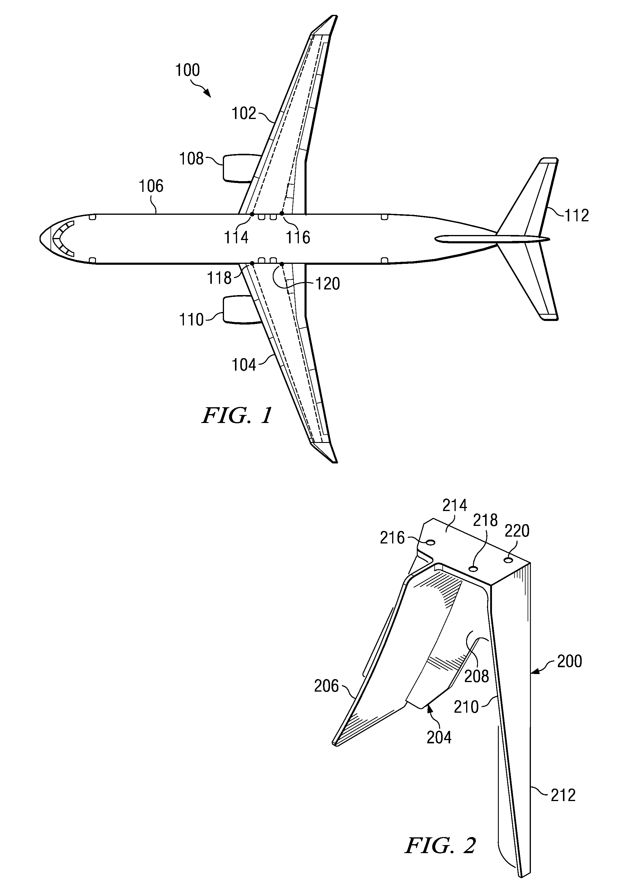
[0043]With reference now to the figures, and in particular, with reference to FIG. 1, a diagram of an aircraft is depicted in which an advantageous embodiment the present invention may be implemented. Aircraft 100 is an example of an aircraft in which a method and apparatus for attaching a wing to a body may be implemented. In this illustrative example, aircraft 100 has wings 102 and 104 attached to body 106. Aircraft 100 includes wing mounted engine 108, wing mounted engine 110, and tail 112.

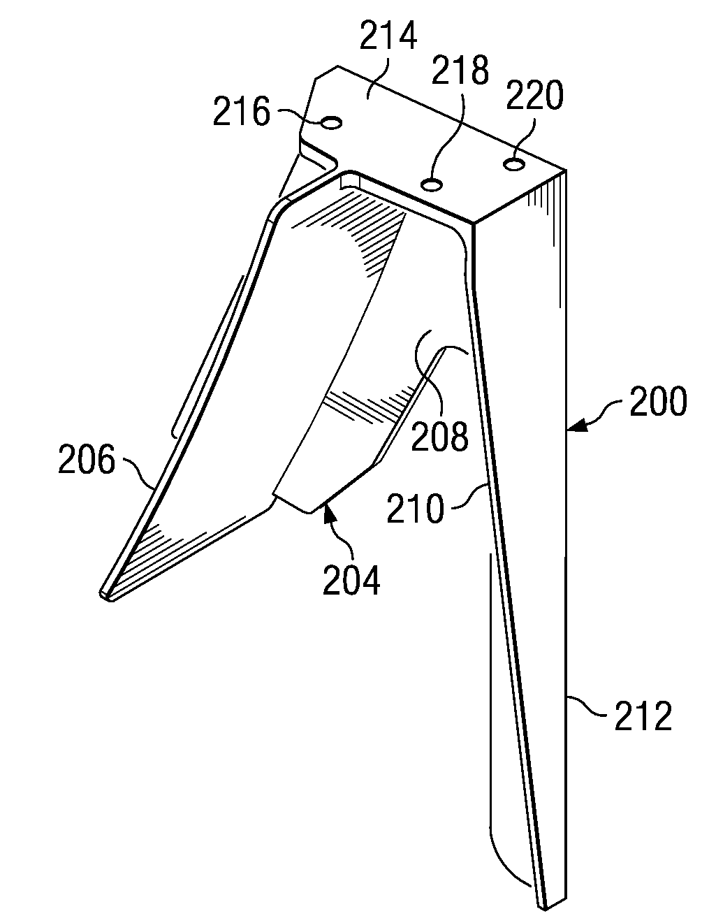
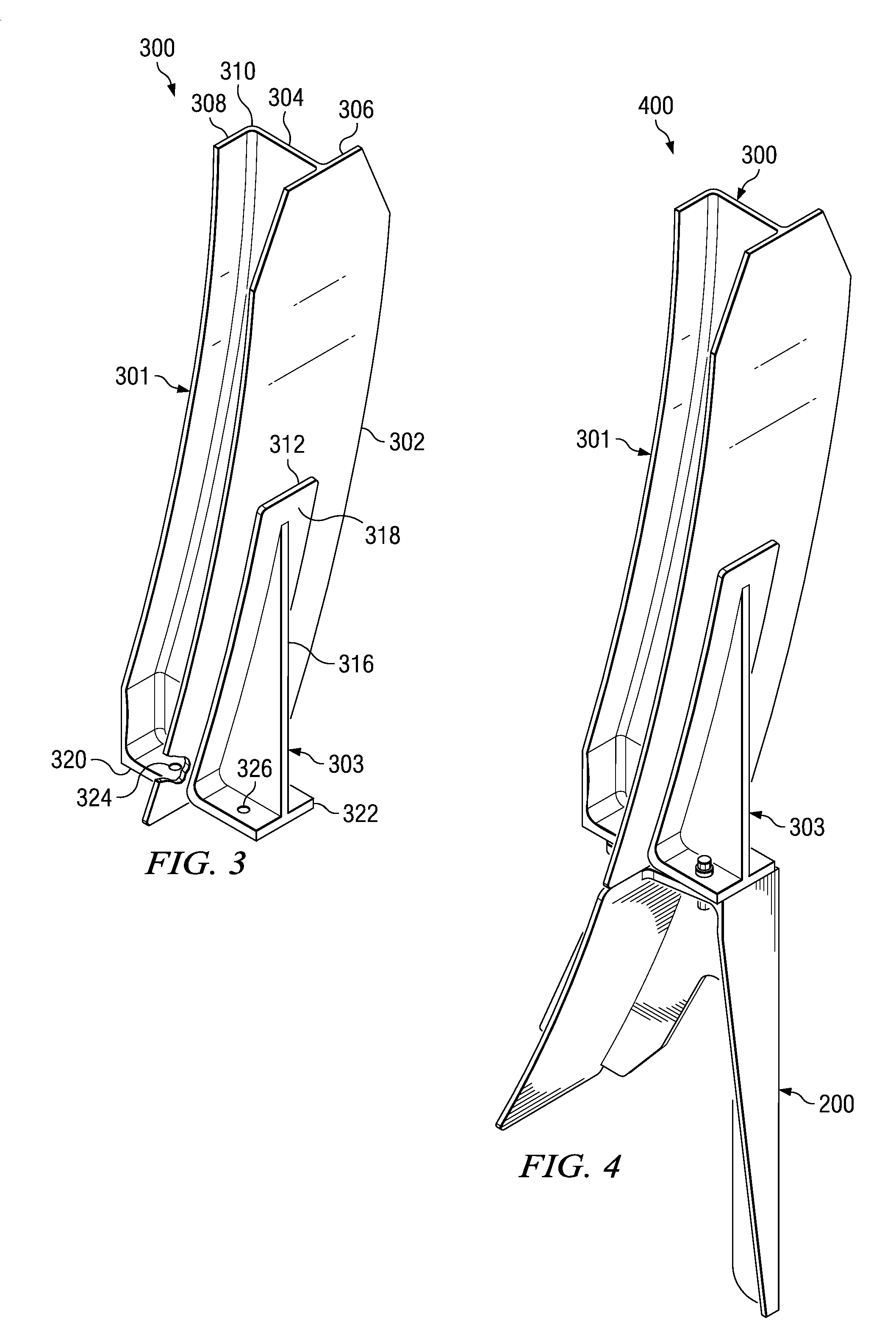
[0044]In particular, the different advantageous embodiments may be used to connect structural components in wings 102 and 104 to structural components in body 106. For example, the different advantageous embodiments may be used in wing spar to body joints which may be located at points 114, 116, 118, and 120. These wing spar to body joints are used to attach the wing spars for wings 102 and 104 to a structural component in body 106.

[0045]Wing spars are structural components that are used to for...


PUM


Abstract

A method and apparatus for assembling an aircraft. A wing spar fitting is connected to a spar in a wing for the aircraft. A body frame fitting is connected to a frame in a body for the aircraft. The locations and orientations of the body frame fitting and the wing spar fitting allow for the body frame fitting to be attached to the wing spar fitting when the wing is positioned for attachment to the body of the aircraft. The wing is positioned with respect to the body of the aircraft for attachment to the body. The body frame fitting and the wing spar fitting are attached to each other with a set of fasteners after the body frame fitting is aligned to the wing spar fitting without penetrating any sealed areas in the wing, wherein the wing is attached to the body by a mechanical joint that is formed by the body frame fitting and the wing spar fitting.

Description

BACKGROUND INFORMATION[0001]1. Field[0002]The present invention relates generally to aircraft and more particularly to attaching wings of an aircraft to a body for the aircraft.[0003]2. Background[0004]Final assembly of large aircraft is a complex procedure. The aircraft components are very expensive and have high inventory holding expenses. Further, the aircraft structural joints for attaching wings to a body are required to carry large loads. It is desirable to be able to quickly put together the different components of the aircraft to reduce the amount of time that different components are present in inventory. Thus, it is desirable to quickly assemble components with structural joints that are robust and reliable.[0005]Currently, each major component, such as a wing or body, cannot be fully preassembled before final assembly of the aircraft to increase efficiency. This type of assembly of components allows for inspections and functional testing to be completed at the sub-assembl...

Claims


Application Information

Patent Timeline
IPC IPC(8): B64C1/26
CPCB64C1/26
Inventor GRIEVE, JAMES C.ANDREWS, FRANCIS A.ERICKSON, MARCUS A.
Owner THE BOEING CO
Learn More