
Medical instrument having a separate transmitter for controlling medical treatment software

a technology for medical instruments and software, applied in the field of medical instruments, can solve the problems of limited use of such instruments, limited to patient registration purposes, and difficult sterilization, and achieve the effect of simplifying the use of softwar

Inactive Publication Date: 2008-11-13
BRAINLAB
View PDF6 Cites 25 Cited by
  • Summary
  • Abstract
  • Description
  • Claims
  • Application Information

AI Technical Summary

Benefits of technology

[0008]In other words, the medical instrument includes a transmitter unit that is exchangeable and / or can be provided separately from the instrument and that can be accommodated in the instrument body. A separate, insertable and removable transmitter unit affords many advantages, one of which is that the transmitter unit can be removed from the instrument for sterilization. By removing the transmitter, problems with the sterilization of transmitter parts or energy supplies are removed. Providing the interior receptacle for the transmitter unit does not alter the exterior shape of the instrument, and the instrument can be used normally, with the additional advantage that it can be used to control the software. A single transmitter unit can be used for a plurality of instruments that have been pre-calibrated. Precalibration means that the position of the functional part of the instrument (for example, the tip) relative to the navigation reference marker is known and / or is stored in the navigation system.
[0009]In one example of the instrument, the instrument includes a quick-release cover (for example, a hinged cover, a cap cover or a sliding cover), for closing the interior receptacle. Such quick-release covers provide ease of handling and the transmitter unit can be quickly removed and / or inserted.
[0010]The cover for the interior receptacle can be sealed, and in one example, the transmitter unit is a wireless transmitter unit. In the latter case, it is advantageous if an electrical energy supply (for example, a battery) for the transmitter unit can be inserted and removed with the transmitter unit. The battery also can be provided together with the transmitter unit or arranged on or in it. The instrument can operate wirelessly, and the transmitter unit, which may be difficult to sterilize, is situated in the interior of the instrument, and therefore no longer represents a sterility problem.
[0015]In accordance with another example, a pointing instrument (or pointer) can be tracked by a camera system (a tracking system) using reference markers that are attached to the pointer. This enables the position of the pointer tip to be depicted in data sets of the patient. The software that processes the patient data can be activated using the activating device in the pointer handle, such that the software performs specific steps that previously had to be selected in a more inconvenient manner (for example, using a touch screen monitor of the navigation system). The data may be transmitted wirelessly, and the device may be powered by an energy source arranged in the pointer such that cables do not have to be provided with the pointer. Such a pointer can transmit information concerning the desired software step. The pointer also can combine different selection steps and simplify the use of the software (for example, in steps such as setting a trajectory or acquiring points, one may simply activate a button on the pointer). The navigation system (and / or the system on which the medical treatment software is running) can have a ready-to-receive receiver that can receive the signals from the transmitter unit.

Problems solved by technology

It can be very distracting, however, for surgeons to attend to switching over the software in addition to their operating activities.
The use of such instruments, however, has been limited to patient registration purposes.
The control device for the software is fixedly integrated with the pointer, making sterilization difficult.

Method used


Image

  • Medical instrument having a separate transmitter for controlling medical treatment software
  • Medical instrument having a separate transmitter for controlling medical treatment software
  • Medical instrument having a separate transmitter for controlling medical treatment software

Examples


Embodiment Construction

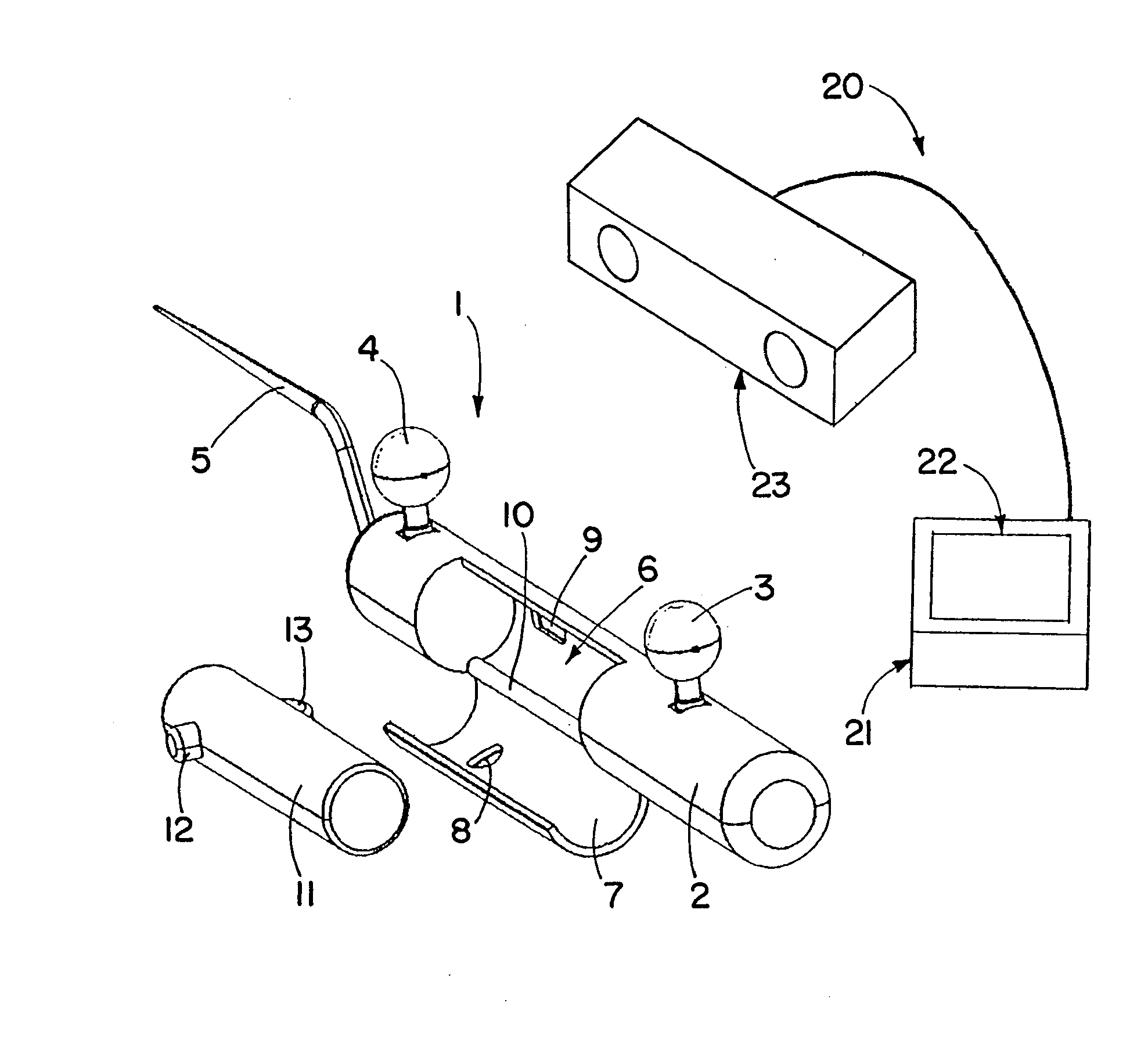
[0021]FIG. 1 illustrates in detail the individual parts of an exemplary instrument 1, e.g., a pointer. The pointer 1 has a handle 2 that forms a casing. Navigation reference markers 3 and 4 are arranged on the handle 2 and in this example are embodied as reflective markers and / or spherical reflectors. The instrument 1 has a pointer tip 5.

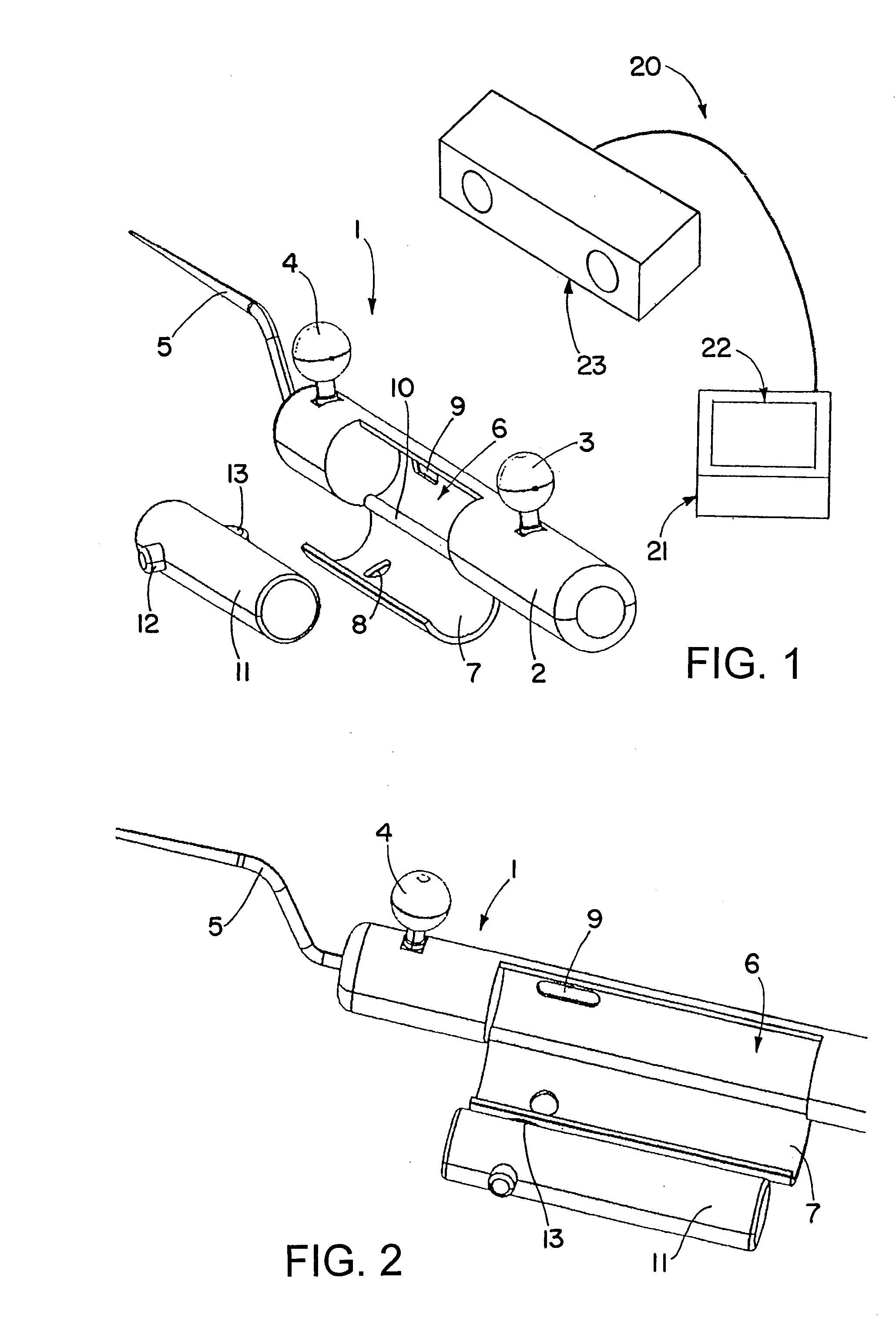
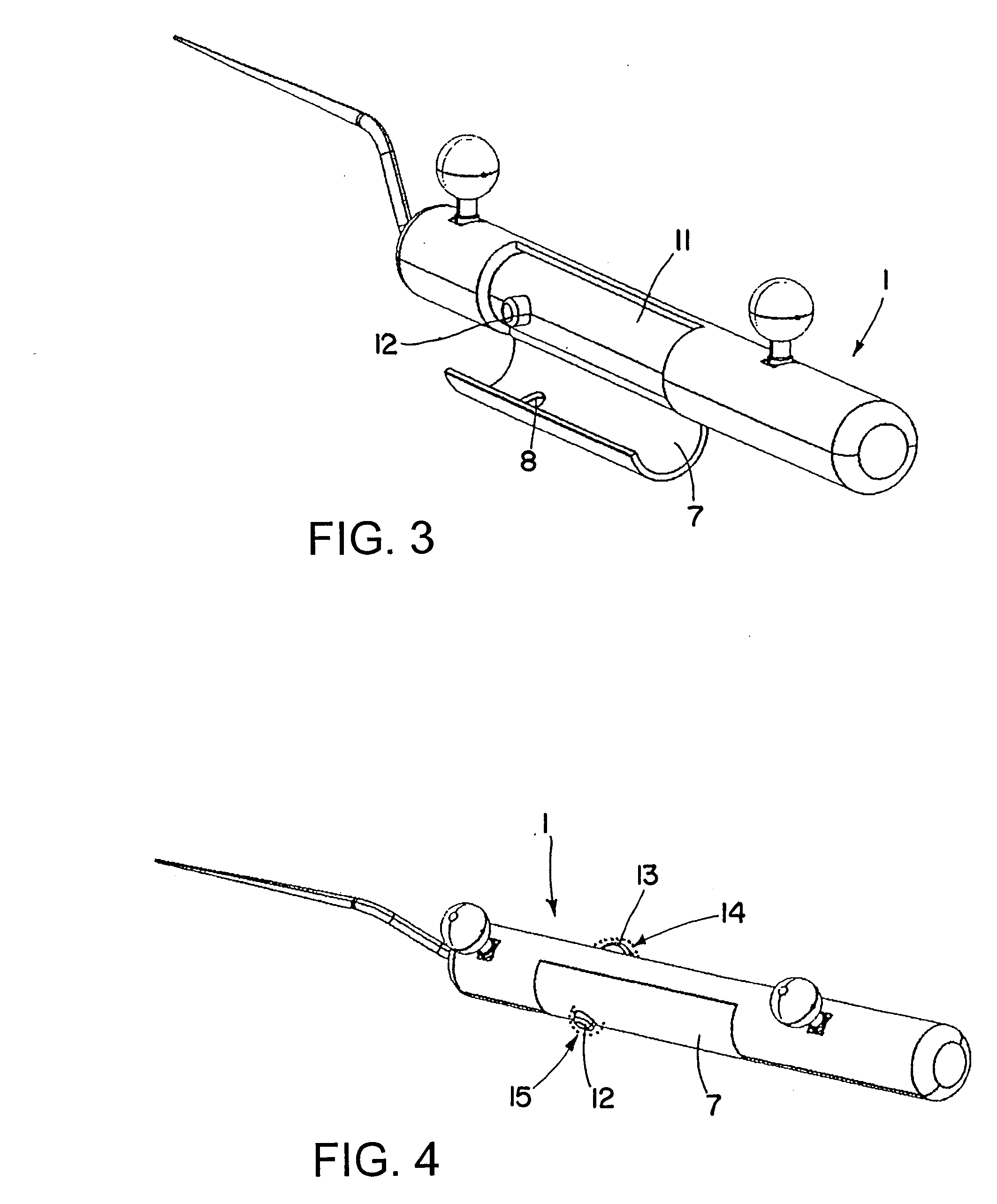
[0022]In its central region, the instrument or the handle 2 comprises an interior receptacle or cavity 6, in this example, a cylindrical hollow space. A cover 7 can be pivoted at a hinge 10 to seal said cavity. The cover 7 and the cavity 6 comprise openings 8 and 9 that will be discussed in more detail below.

[0023]Together with the instrument, FIG. 1 also shows a transmitter unit 11 that is also cylindrically shaped and fits into the interior receptacle 6. An activating device (in this example, a push button 12 and a scroll wheel 13) can rest in the aperture holes 8 and 9. The push button 12 and the scroll wheel 13 protrude slightly from the casing ...


PUM


Abstract

The patent discloses a medical instrument having a control device for controlling medical treatment software, wherein the control device includes a transmitter for transmitting software control signals and at least one control for activating the transmitter. The transmitter may be provided as a separate transmitter unit, and the instrument may include a closable interior receptacle, wherein the transmitter unit can be inserted into and removed from the interior receptacle.

Description

RELATED APPLICATION DATA [0001]This application claims priority of U.S. Provisional Application No. 60 / 939,213 filed on May 21, 2007, and EP 07009316 filed on May 9, 2007, which are incorporated herein by reference in their entirety.FIELD OF THE INVENTION [0002]The invention relates to a medical instrument including a control device for controlling medical treatment software. It also relates to a system of such instruments.BACKGROUND OF THE INVENTION [0003]In computer-assisted surgery, a navigation and / or tracking system in an operating theater provides a surgeon with different image outputs. These image outputs represent patient data sets or at least parts of them. For example, the outputs may depict three-dimensional or sectional representations of parts of the patient's body. The patient data sets can be produced either by imaging methods such as CT or MR tomography, x-ray, ultrasound or fluoroscopy, or by image-free methods such as tapping the surface of a bone using a registere...

Claims


Application Information

Patent Timeline
IPC IPC(8): G06F3/00
CPCA61B19/52A61B19/5244A61B2019/5255A61B2019/5268A61B90/36A61B2034/2055A61B2034/2068A61B34/20
Inventor HAGER, STEFANURBAN, ALEXANDER
Owner BRAINLAB
Learn More