Ink jet recording ink tank

Active Publication Date: 2008-11-13
CANON KK
View PDF29 Cites 7 Cited by
  • Summary
  • Abstract
  • Description
  • Claims
  • Application Information

AI Technical Summary

Benefits of technology

[0013]A first problem to be solved by the present invention is how to focus on a relationship between a negative pressure generating member of an ink tank and the physical property of ink to provide an innovative ink tank, one which can both reliably counter shocks during physical distribution and ensure that ink will continue to be efficiently used until the supply is exhausted.
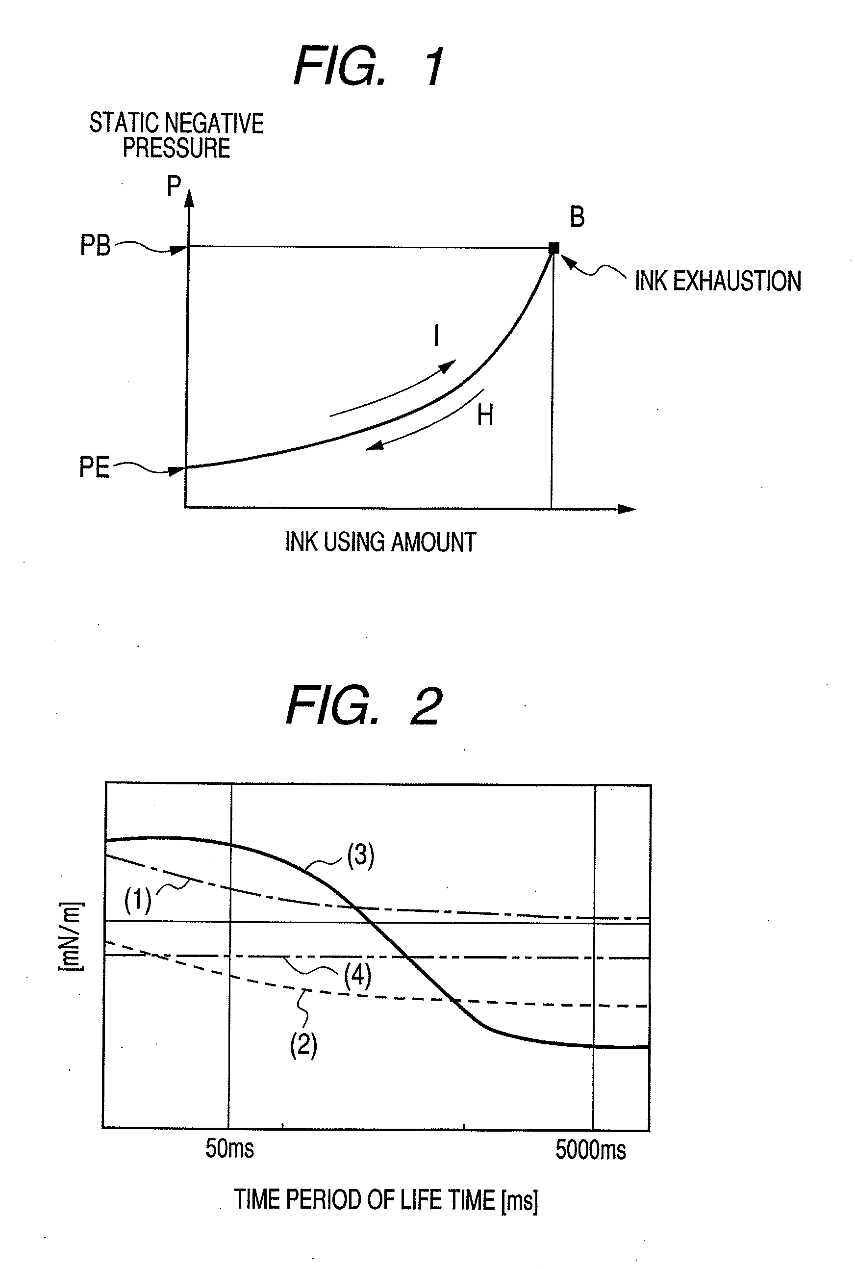
[0014]According to the present invention, in order to resolve the above described ink tank problems by employing the interfacial tension of an ink absorbent member and the physical property of ink, the migration of ink was analyzed, for the above described individual environments, by focusing on the dynamic surface tension of ink and the correlation between the dynamic surface tension and the absorption characteristic of an ink retention member. And the following view was obtained as to ink having a change in dynamic surface tension. That is, when the surface tension is high for dynamic movement during the initial displacement, ink in the ink retention member, especially at the gas-liquid interface, tends to be difficult to move, and effects are generated that suppress the leakage of ink while countering the effects of shock. On the other hand, the displacement of ink while filling the ink tank and while supplying ink from the ink tank to the recording head is a steady displacement that continues for a comparatively extended period of time, compared with the initial displacement, which occurs within a very short period of time. When during the steady displacement period the dynamic surface tension is low, the filling of the ink retention member, the permeability relative to the ink retention member and the supply of ink to the recording head are satisfactory. And since shock that occurs during physical distribution, or upon the mounting of the recording head in a recording apparatus, corresponds to the initial displacement, when ink having a dynamic surface tension change property that can proportionally cope with both initial displacement and steady displacement is employed, solutions for the above described problems can be achieved. As a result, the degree of freedom available, in the design of the structure and the shape of the ink tank and in the selection of a material to be used for the ink retention member, is also increased. The present invention is provided based on the above described view.
[0016]By the present invention, an ink tank which can both reliably counter shocks during physical distribution and ensure that ink will continue to be efficiently used until the supply is exhausted is provided, in view of a relationship between a negative pressure generating member of an ink tank and the physical property of ink.

Problems solved by technology

That is, when the surface tension is high for dynamic movement during the initial displacement, ink in the ink retention member, especially at the gas-liquid interface, tends to be difficult to move, and effects are generated that suppress the leakage of ink while countering the effects of shock.

Method used


Image

  • Ink jet recording ink tank
  • Ink jet recording ink tank
  • Ink jet recording ink tank

Examples


examples

[0132]The present invention will be described more specifically by employing examples and comparison examples; however, without departing from the subject, the present invention is not limited to these examples. In the following description, “part” and “%” are provided based on a mass reference, unless an explanatory note is given.

[0133](Prepare Test Ink)

[0134]The individual elements shown in Table 1 were mixed and well agitated, the mixture was filtered using a micro filter (produced by Fuji Film Corp.) having a pore size of 0.2 μm, and test inks 1 to 6 were obtained. Table 1 shows the compositions of test inks 1 to 6. In Table 1, EMULMIN NL80 and EMULMIN L90S are surfactants produced by Sanyo Chemical Industries, Ltd. EMALEX1615 and EMALEX1815 are surfactants produced by Nihon Emulsion, Co., Ltd, and ACETYLENOL E-100 is a surfactant produced by Kawaken Fine Chemicals Co., Ltd.

TABLE 1Ink compositionInk1234567DBL 1993333333Glycerin10101010101010Diethylene glycol101010101010101,2-hex...


PUM


Abstract

An ink jet recording ink tank includes: an ink retention member, which to hold ink exerts a negative pressure through capillary force; and ink, which is retained in the ink retention member, for which a dynamic surface tension in a lifetime of 50 msec, obtained by a maximum bubble pressure method, is higher than an interfacial tension of the ink retention member, a dynamic surface tension in a lifetime of 5000 msec is lower than the interfacial tension of the ink retention member, and a difference between the dynamic surface tension in the lifetime of 50 msec and the dynamic surface tension in the lifetime of 5000 msec is equal to or greater than 8 mN / m.

Description

BACKGROUND OF THE INVENTION[0001]1. Field of the Invention[0002]The present invention relates to an ink jet recording ink tank, employed for an ink jet recording apparatus that performs a recording operation by discharging a liquid, such as ink.[0003]2. Description of the Related Art[0004]Conventionally, ink tanks, employed to supply ink to the recording heads of apparatuses to record data on a variety of print media and other materials, can roughly be categorized as being one of two types, depending on the ink storage method used.[0005]The first type is one wherein an ink tank, in which ink is stored, is incorporated within the main body of an apparatus, and a tube, for example, is employed as an ink supply path leading from the ink tank to a recording head.[0006]The second type is one that employs an ink absorbent member, arranged so as to cover an entire ink tank, and that uses capillary force to draw in and retain ink, and the capillary force is balanced between the ink absorben...

Claims


Application Information

Patent Timeline
IPC IPC(8): B41J2/175B41J2/01
CPCB41J2/17556C09D11/30
Inventor SANADA, MIKIOMORIBE, KENJIYANAGIMACHI, SATOMINAKAGAWA, KOUHEIMORI, YASUHITO
Owner CANON KK
Why Eureka
Try Eureka