
Fiber optic cables and assemblies and the performance thereof

a technology of fiber optic cables and jumpers, applied in the direction of optics, fibre mechanical structures, instruments, etc., can solve the problems of physical and performance limitations, optical fibers are one limiting factor in the evolution of fiber optic networks, etc., to reduce component size, reduce the effect of bending radius tolerance, and reduce the size of components

Active Publication Date: 2008-11-06
CORNING OPTICAL COMM LLC
View PDF33 Cites 24 Cited by
  • Summary
  • Abstract
  • Description
  • Claims
  • Application Information

AI Technical Summary

Benefits of technology

[0006]To achieve the foregoing and other objects, and in accordance with the purposes of the invention as embodied and broadly described herein, the present invention provides various embodiments of fiber optic cables, jumpers and other assemblies including bend performance optical fiber in at least a portion thereof. The present invention further provides bend performance optical fiber suitable for use in fiber optic cables, fiber optic hardware and other assemblies, wherein the bend performance optical fiber comprises certain physical and performance characteristics that lends itself to reduced component size, tighter bend radius tolerances without degraded performance, and relaxes fiber routing and handling requirements.

Problems solved by technology

In other words, it is oftentimes the case that the physical and performance limitations of the optical fibers partly define assembly structure and processes associated with manufacturing said assemblies.
Thus, optical fibers are one limiting factor in the evolution of fiber optic networks.

Method used


Image

  • Fiber optic cables and assemblies and the performance thereof
  • Fiber optic cables and assemblies and the performance thereof
  • Fiber optic cables and assemblies and the performance thereof

Examples


Embodiment Construction

[0022]The present invention will now be described more fully hereinafter with reference to the accompanying drawings in which exemplary embodiments of the invention are shown. However, the invention may be embodied in many different forms and should not be construed as limited to the embodiments set forth herein. These exemplary embodiments are provided so that this disclosure will be both thorough and complete, and will fully convey the scope of the invention and enable one of ordinary skill in the art to make, use and practice the invention. Like reference numbers refer to like elements throughout the various drawings.

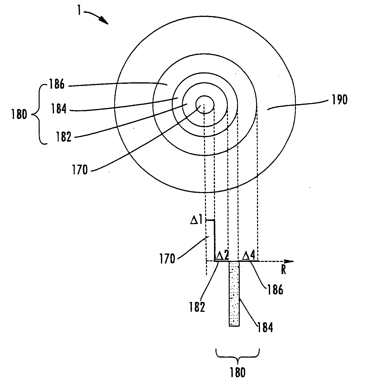
[0023]FIG. 1 depicts a representation of a bend performance optical fiber 1 suitable for use in fiber optic cables, cables assemblies, fiber optic hardware and other network components of the present invention. The present invention is advantageous because it permits assemblies having aggressive bending / installation solutions while optical attenuation remains extreme...


PUM


Abstract

A fiber optic cable having at least one optical fiber such as a microstructured bend performance optical fiber disposed within a protective covering. The protective covering is highly flexible and the fiber optic cable has extremely low delta attenuation when aggressively bent compared with the conventional fiber optic cable designs. By way of example, the delta attenuation of one fiber optic cable design is about 0.33 dB or less when wrapped 3 turns about a 7.5 millimeter mandrel at a reference wavelength of 1625 nanometers. Other variations of the present invention include a connector attached to the fiber optic cable.

Description

CROSS-REFERENCE TO RELATED APPLICATIONS[0001]The present application incorporates by reference U.S. patent application entitled “HIGH DENSITY FIBER OPTIC HARDWARE”, filed even day herewith and assigned to Corning Cable Systems LLC.FIELD OF THE INVENTION[0002]The present invention relates generally to fiber optic cables and jumper assemblies and the performance thereof. By way of example, the invention is related to assemblies such as optical fiber jumpers having at least one bend performance optical fiber, thereby enabling previously unattainable optical performance characteristics.BACKGROUND OF THE INVENTION[0003]Along with the increase in the deployment of “Fiber-to-the-Premises” (FTTP) optical networks, a need has arisen for increasing the performance, manageability, handleability and flexibility of fiber optic cables, cable assemblies and network components in general. With respect to outdoor installation environments, cables, cable assemblies and other network components are be...

Claims


Application Information

Patent Timeline
Patent Type & Authority Applications(United States)
IPC IPC(8): G02B6/44
CPCG02B6/02357G02B6/02366G02B6/4402G02B6/4432
Inventor REGISTER, JAMES A.
Owner CORNING OPTICAL COMM LLC
Learn More