
Monitoring or imaging system with interconnect structure for large area sensor array

a sensor array and monitoring system technology, applied in the field of large area array monitoring or imaging systems, can solve the problems of weak signals received from the transducer assembly, rf interference, undetectable low s/n ratio,

Active Publication Date: 2008-11-06
GENERAL ELECTRIC CO
View PDF21 Cites 46 Cited by
  • Summary
  • Abstract
  • Description
  • Claims
  • Application Information

AI Technical Summary

Benefits of technology

[0009]In one form of the invention, an ultrasonic monitoring system is formed with a probe unit having an array of transducer cells arranged in rows and columns and formed along a first plane with a first pitch along a first direction. An integrated circuit including an array of circuit cells is formed along a second plane parallel to the first plane. The circuit cells are spaced apart along the first direction at a second pitch smaller than the first pitch. A first of the transducer cells is vertically aligned, along a direction normal to one of the planes, with a first of the circuit cells and h

Problems solved by technology

Furthermore, signals received from the transducer assembly may be weak, subject to RF interference and may exhibit an undesirably low S / N ratio.

Method used


Image

  • Monitoring or imaging system with interconnect structure for large area sensor array
  • Monitoring or imaging system with interconnect structure for large area sensor array
  • Monitoring or imaging system with interconnect structure for large area sensor array

Examples


Embodiment Construction

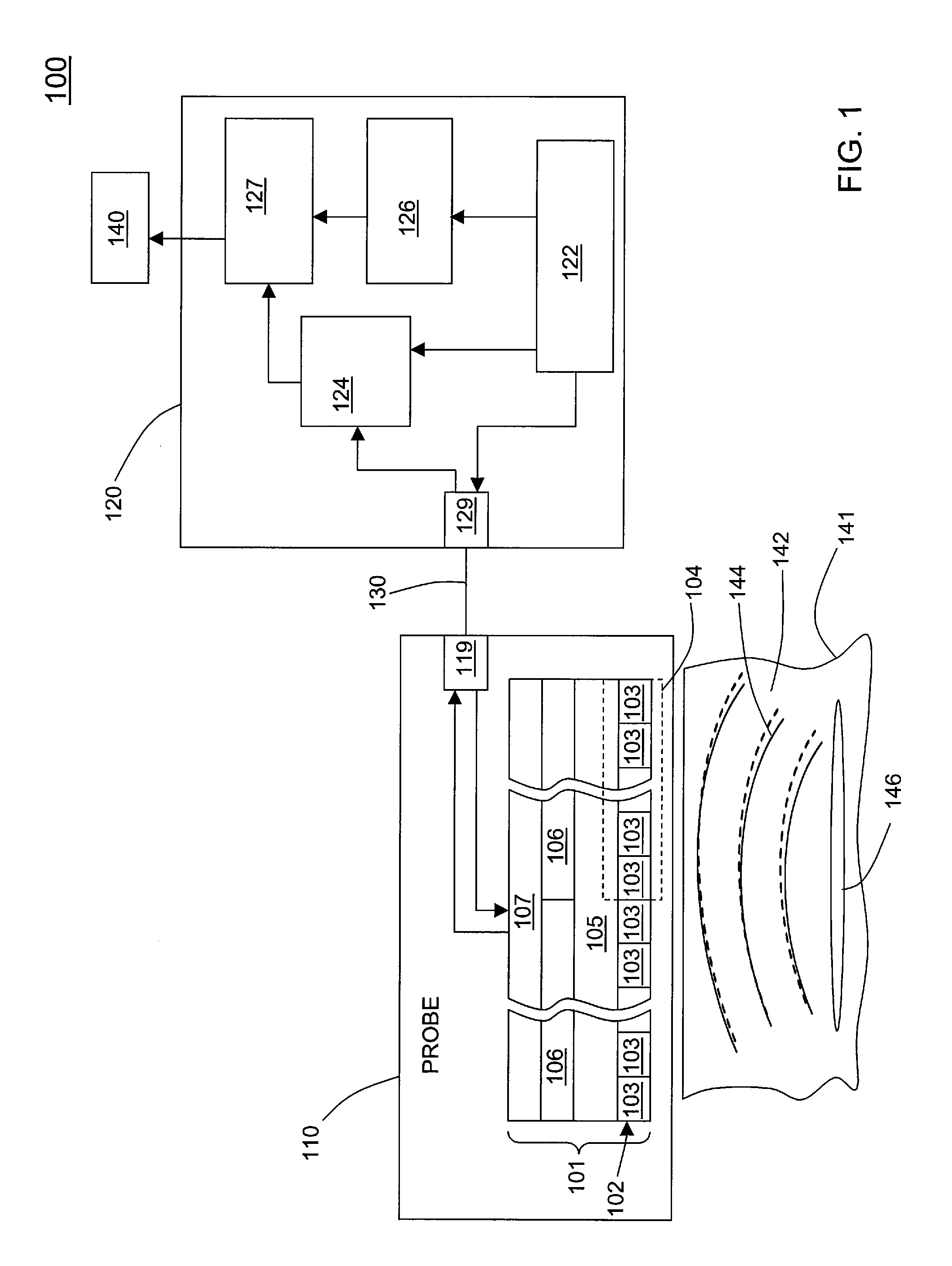
[0021]FIG. 1 illustrates an exemplary ultrasound monitoring system 100, in this example, one of the type used for medical imaging, having a probe unit that is relatively light and suitable for hand-held use. More generally, embodiments of the invention include, but are not limited to, acoustic monitoring or imaging systems which, generally, incorporate large arrays of transducers.

[0022]The system 100 includes a probe unit 110 connected to a system console 120 by a multi-channel cable 130 and a display 140 connected to the console 120. The probe unit 110 comprises a transducer assembly 101 having an array 102 of transducer cells 103, a connector 105, a plurality of Application Specific Integrated Circuits (ASICs) 106, and an interconnection structure 107. The console 120 includes a system controller 122, a main beamformer 124, an image processor 126, and a scan converter 127. The transducer cell array 102 includes a plurality of transducer subarrays 104, each containing a like number...


PUM


Abstract

An ultrasonic monitoring system is formed with a probe unit. In one example an array of transducer cells is arranged in rows and columns formed along a first plane with a first pitch along a first direction. An integrated circuit including an array of circuit cells is formed along a second plane parallel to the first plane. The circuit cells are spaced apart along the first direction at a second pitch smaller than the first pitch. A first of the transducer cells is vertically aligned, along a direction normal to one of the planes, with a first of the circuit cells and having a connection thereto. A second of the transducer cells is offset from vertical alignment with respect to the position of a second circuit cell so as to not overlie the second circuit cell. A connection subsystem is positioned between the array of transducer cells and the array of circuit cells, configured to form connection of the first transducer cell to the first circuit cell and connection of the second transducer cell with the second circuit cell.

Description

BACKGROUND OF THE INVENTION[0001]1. Field of the Invention[0002]This invention relates generally to large area array monitoring or imaging systems of the type used for ultrasound or x-ray analysis and, more particularly, to systems and methods which combine high density transducer arrays with processing circuitry.[0003]2. Background Art[0004]Ultrasound monitoring and imaging systems use transducer arrays to create short high frequency acoustic pulses which undergo reflection from surface interfaces at which there are changes in acoustic impedance. The transducers convert reflected energy into electrical signals which are processed to generate two-dimensional or three-dimensional image information descriptive of a subject under study.[0005]Acoustic transducer cells are typically multi-layered structures comprising piezoelectric or micro-machined transducers configured with electronic circuitry in a probe assembly. The electrical signals are further processed by beam forming circuitry...

Claims


Application Information

Patent Timeline
IPC IPC(8): H02N2/00
CPCA61B8/0833A61B8/4483B06B1/0629H01L27/0207H01L27/11803H01L27/14634
Inventor WODNICKI, ROBERT GIDEONMILLS, DAVID MARTINFISHER, RAYETTE ANNWOYCHIK, CHARLES GERARD
Owner GENERAL ELECTRIC CO
Learn More