
Apparatus and method for controlling brightness of light source and displaying apparatus

a technology of apparatus and light source, applied in the direction of optical radiation measurement, instruments, photometry, etc., can solve the problems of affecting the conventional controlling method, the analog control signal is required, and the led color offset occurs, so as to reduce noise interference and enhance detection accuracy

Inactive Publication Date: 2008-11-06
NOVATEK MICROELECTRONICS CORP
View PDF4 Cites 35 Cited by
  • Summary
  • Abstract
  • Description
  • Claims
  • Application Information

AI Technical Summary

Benefits of technology

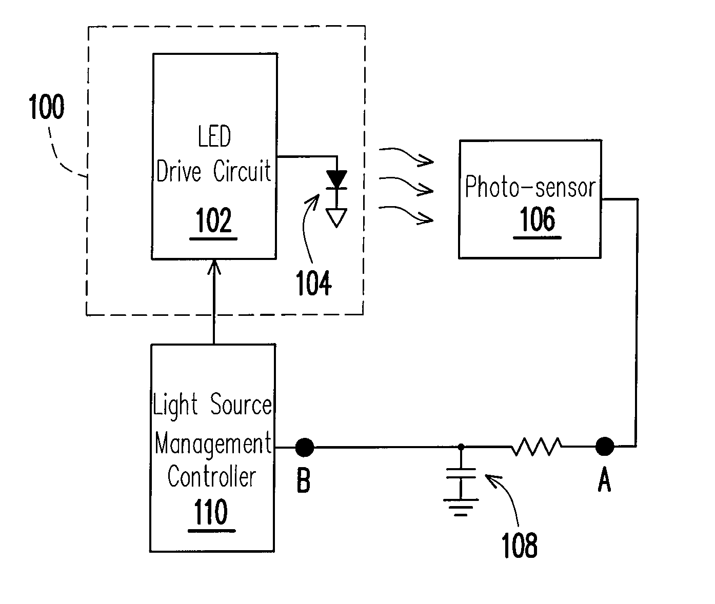
[0013]The present invention is directed to an apparatus for controlling brightness of a light source, which may effectively reduce noise interference and enhance detection accuracy.
[0014]The present invention is directed to a method for controlling brightness of a light source, which may effectively reduce noise interference and enhance detection accuracy.
[0015]The present invention is directed to a light source system having a stable display effect.

Problems solved by technology

The disadvantage of the analog modulation method lies in that, the LED color offset occurs and an analog control signal is required.
However, the conventional controlling method is affected by system noises caused by a driver when the light source is lightened.
However, the output signal itself detected by the photo-sensor is a weak electric signal, and the conventional controlling method is to sample the data when the LED light source is lightened with large noise.
This reduces the signal-to-noise ratio of the detection signal and affects the accuracy of an actual detected result.
Especially, a large-scale LED matrix light source requires a large drive current, and accordingly, the noises generated in the circuit system are even larger, which possibly overwhelms the detected output signal, and even causes that the required feedback signal cannot be detected.

Method used


Image

  • Apparatus and method for controlling brightness of light source and displaying apparatus
  • Apparatus and method for controlling brightness of light source and displaying apparatus
  • Apparatus and method for controlling brightness of light source and displaying apparatus

Examples


Embodiment Construction

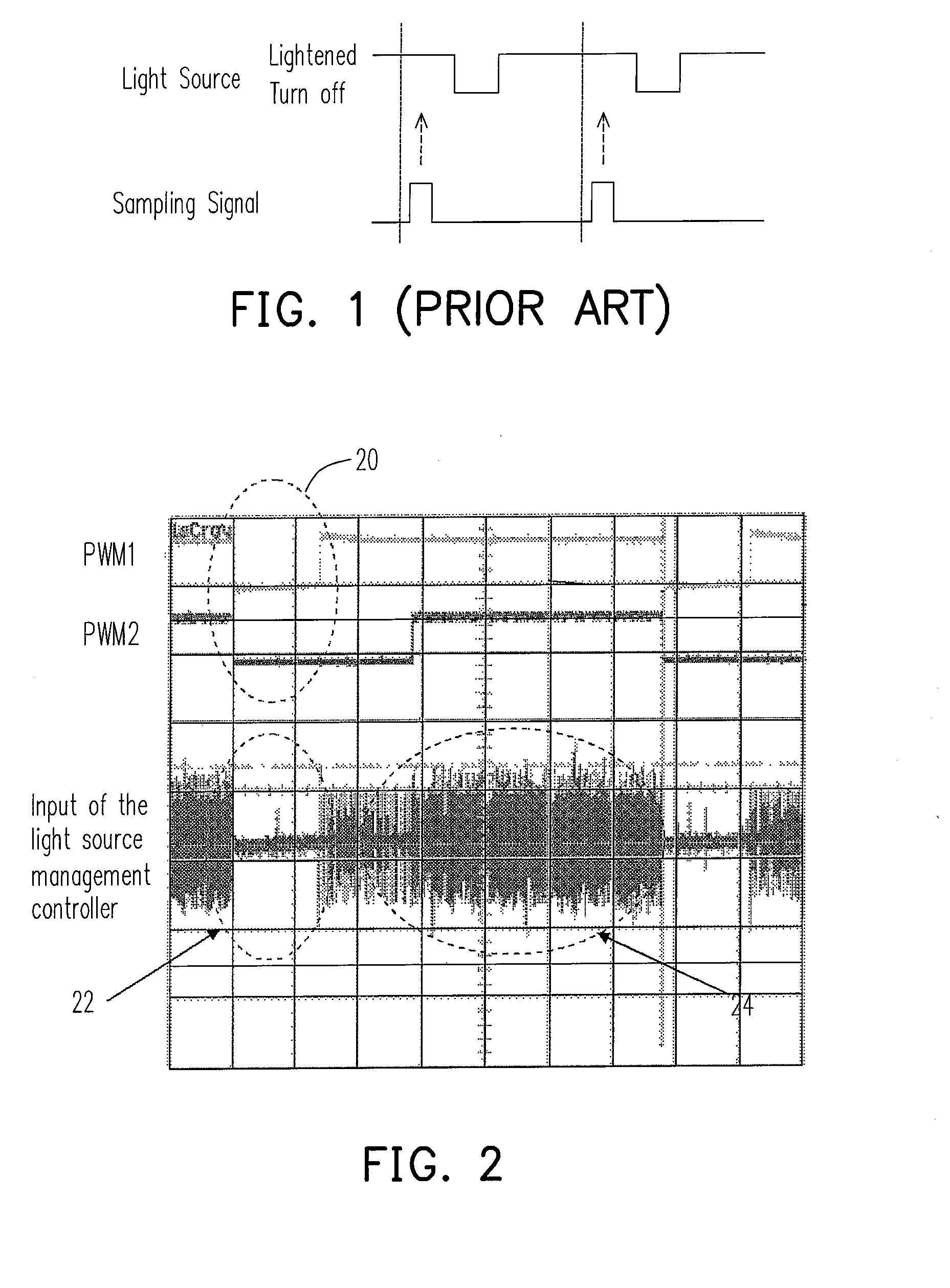
[0032]In order to solve the problem of a change of a light source, it is further researched deeply in the present invention. FIG. 2 is a schematic view of the relationship between the state of a light source and noises of a measurement signal for the light source. Referring to FIG. 2, for example, two LEDs having different colors are controlled by voltage modulation signals PWM1 and PWM2, respectively. In a time region 20, both the LEDs are in an OFF state, i.e., the light source is fully turned off. In addition, both the LEDs are in an ON state in the time region where the PWM1 and PWM2 are in a high level. After a change of the light source is converted into an electrical signal through the photo-sensor, the electrical signal passes through a filter to obtain a light intensity signal, which is commonly used as an input signal for a light source management controller. A signal in the region 22 is corresponding to a state 20 that light emitting elements are all turned off, and a sig...


PUM


Abstract

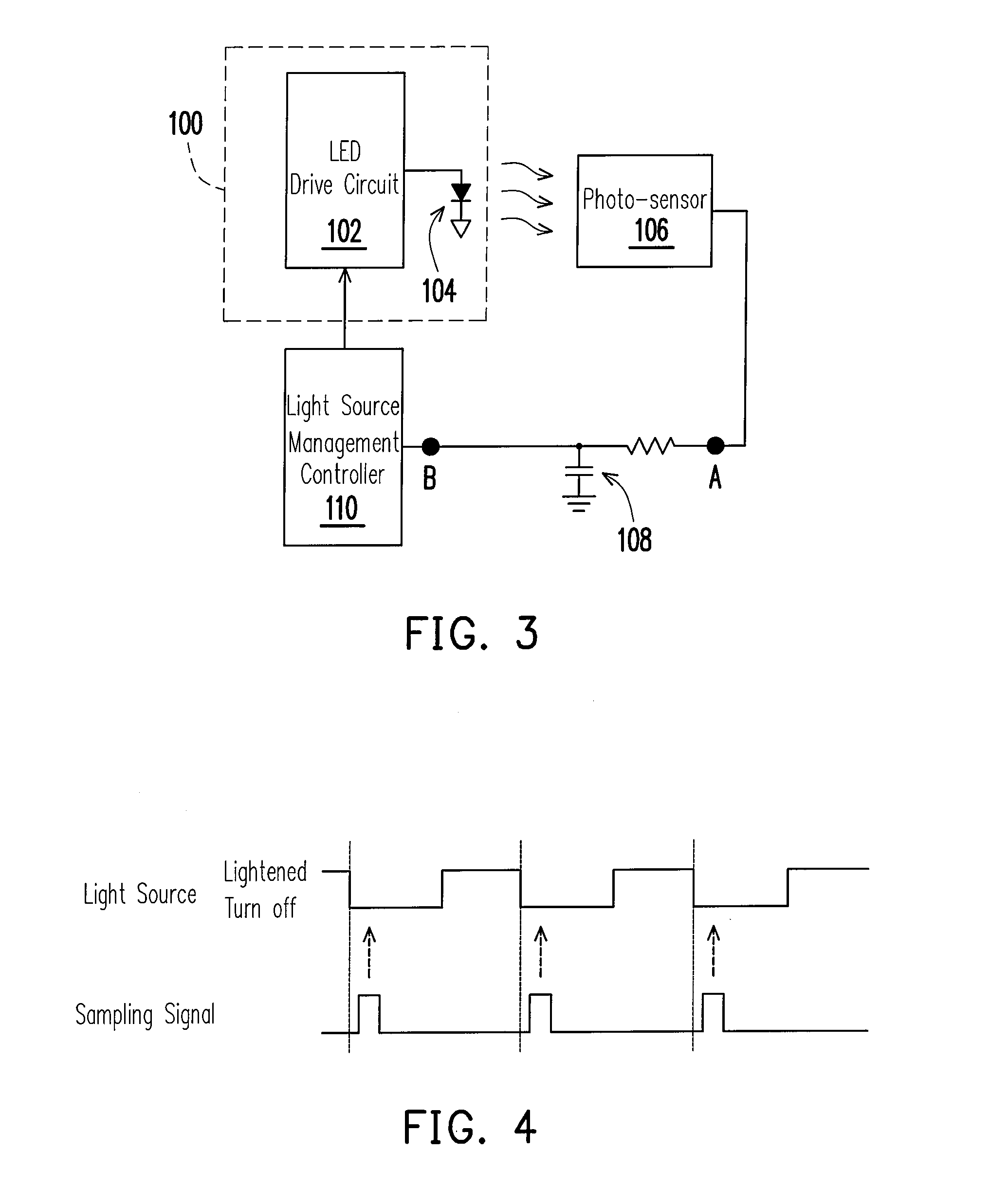
The invention provides a method and apparatus for controlling brightness of illumination systems, illumination systems and display using the same. The apparatus includes a photo-sensor and a control circuit. The photo-sensor detects a luminous output of the illumination systems and correspondingly outputs a detection signal. The control circuit gets the detection signal during the light source being turned off, and adjusts and controls the brightness according this feedback signal. The method and apparatus of the invention can offer a stable output to illumination systems and displays using the same.

Description

CROSS-REFERENCE TO RELATED APPLICATION[0001]This application claims the priority benefit of Taiwan application serial no. 96115635, filed May 2, 2007. All disclosure of the Taiwan application is incorporated herein by reference.BACKGROUND OF THE INVENTION[0002]1. Field of the Invention[0003]The present invention relates to an apparatus and a method for controlling a light source, and more particularly to an apparatus for controlling the brightness of a light emitting diode (LED) light source, a light source system and a display apparatus using the same, and a controlling method thereof.[0004]2. Description of Related Art[0005]An LED with a low working voltage (only 1.5-3V) is capable of actively emitting lights, and has a specific brightness, which may be adjusted through adjusting a voltage or a current, and meanwhile, the LED has advantages of impact resistance, anti-vibration, and a long service life (100,000 hours). Therefore, the LED has been widely used in various terminal dev...

Claims


Application Information

Patent Timeline
Patent Type & Authority Applications(United States)
IPC IPC(8): G01J1/32
CPCG01J1/32H05B33/0818H05B33/0869H05B45/22
Inventor WEI, HSIEN-WANG
Owner NOVATEK MICROELECTRONICS CORP
Learn More