Tie-down anchor system and method
a technology of tie-down anchors and rings, which is applied in the direction of packaging, cargo supporting/securing components, flexible elements, etc., can solve the problems of permanent damage to the surface, difficult manufacturing, and difficult mounting of prior art systems, so as to achieve maximum convenience and strength, minimal failure, and maximum longevity
- Summary
- Abstract
- Description
- Claims
- Application Information
AI Technical Summary
Benefits of technology
Problems solved by technology
Method used
Image
Examples
first embodiment
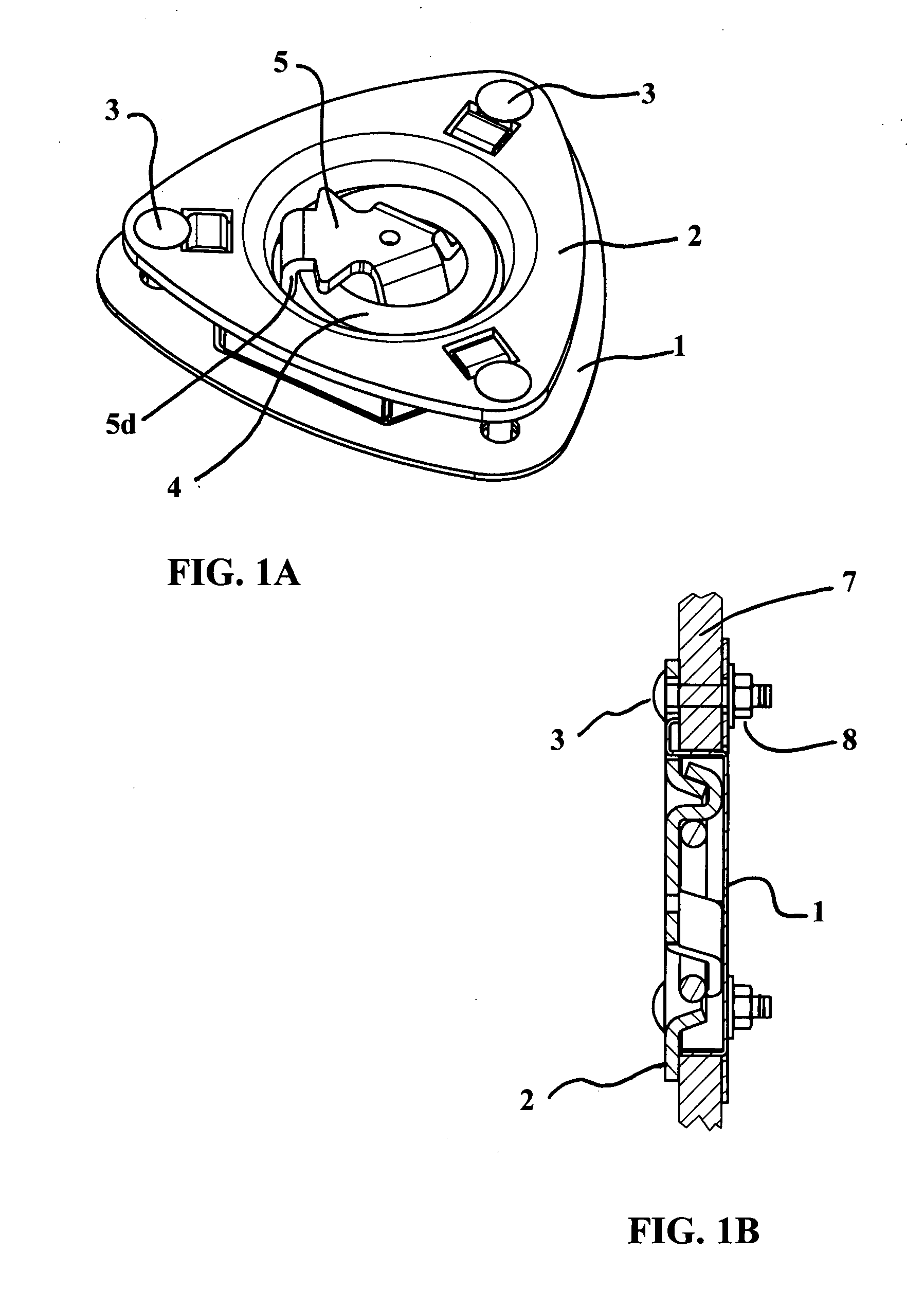
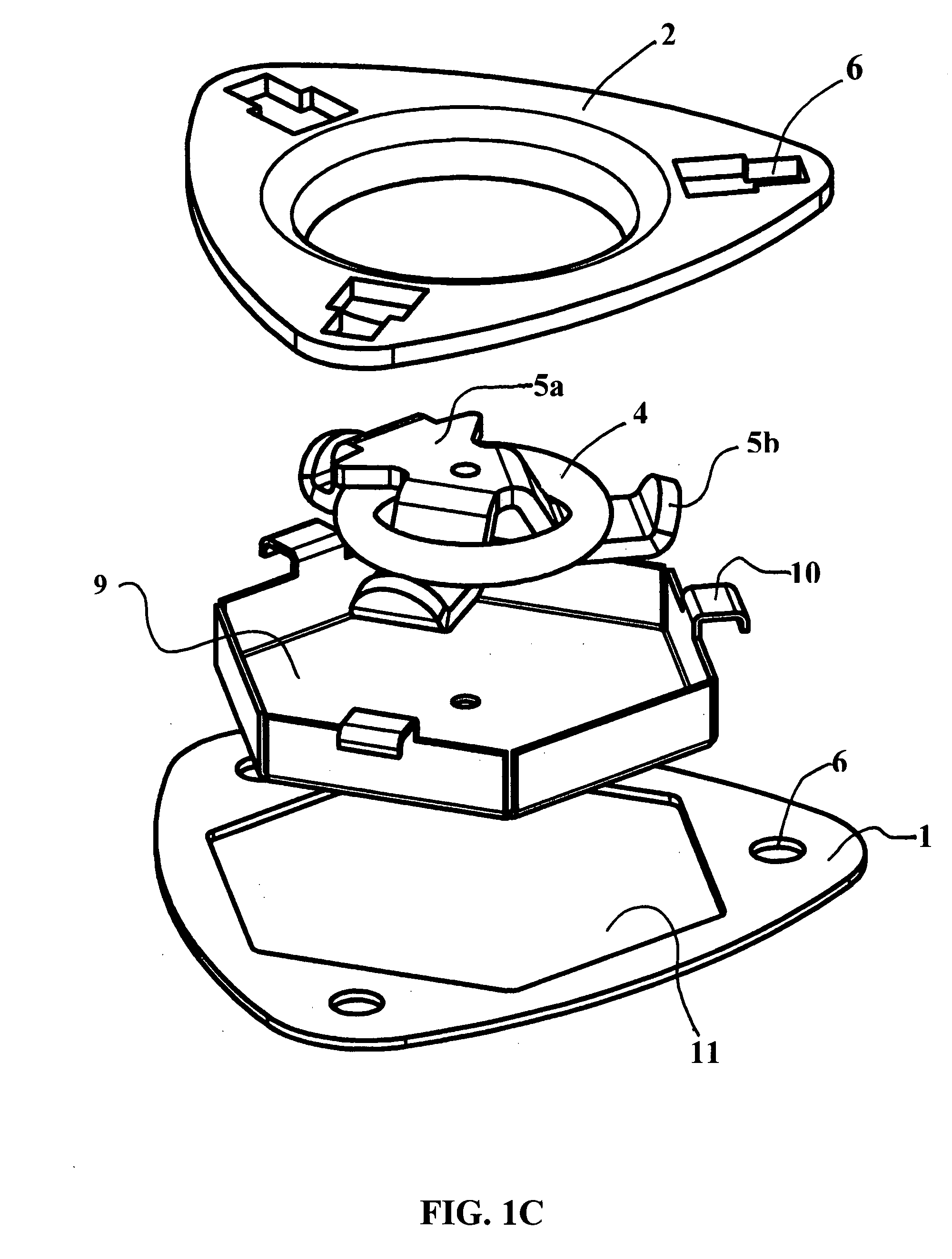
[0040]Turning to FIGS. 1A-1E, the invention can be seen. FIG. 1A shows a perspective view of this embodiment. This particular embodiment requires a recess in the mounting surface 7 for the anchor device. The recess must be large enough to allow the retaining cup 9 shown in FIG. 1C to pass through. A backing plate 1 that is normally mounted behind the mounting surface cooperates with a top mounting flange 2 that is secured through the surface to the plate 1 with three bolts 3 to tightly mount the device. The preferred bolt is a 5 / 16-18 carriage bolt; however, any bolt is within the scope of the present invention. The mounting flange 2 contains square holes 6 that receive the carriage bolts and prevent rotation when securing fasteners / hex nuts. 3. The “double-square” shaped holes accept and reveal the tabs of the retaining cup and the heads of the carriage bolts function to fasten and clamp the retaining cup. These holes 6 can be adapted to allow space for attachment flanges 10 (FIG. ...
second embodiment
[0043]Turning to FIGS. 2A-2E, the invention can be seen. This embodiment also provides a rotating ring without the use of axles or pins; however, this embodiment does not require recessing. A flat backing plate 1, with normally no holes other than the bolt holes 6, in cooperation with a top mounting flange 2 sandwiches a surface 7 using bolts 3 and nuts 8. The flange 2 has a raised area 2a with lower supports 2b that transition through steps 2c. The raised area 2a provides space for a rotating mount 5 to be held in place but still free to rotate.
[0044]The rotating mount 5 has a flat top area 5a with descending sides 5f and at least two flat feet 5b (FIG. 2C). One end of this rotating mount 5 can contain a protruding nose 5c with a descending lip 5d and notch 5e. The legs 5b hold the rotating mount 5 under the mounting flange 2, while the particular shape of the mounting flange 2 allows the mount 5 to rotate by not pinching it. The notch 5e and descending lip 5d receive an anchor rin...
fourth embodiment
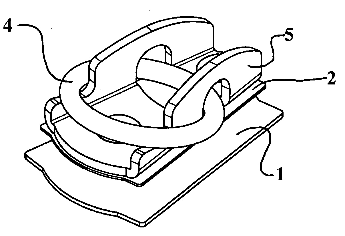
[0047]the present invention is shown in FIGS. 4A-4G and includes a pair of flat plates, namely a front plate 2 and a back plate 1 that engage and sandwich a mounting surface 7. A ring clip 5 mounts above the front plate 2 trapping / retaining an anchor ring 4 with a pair of bolts 3 passing through the ring clip 5, the top plate 2 and the back plate 1. These bolts 3 receive nuts 8 to mount the arrangement. An anchor ring 4 passes through a notch 5e in the ring clip 5. The ring 4 is free to rotate forward and backward in this notch 5e. The preferred bolt is a 5 / 16-18 carriage bolt with a washer and a 5 / 16-18 nut. Any type of bolts and nuts are within the scope of the present invention.
[0048]Turning to FIGS. 5A-5C and 6A-6C, a fifth and sixth embodiment of the present invention can be seen. In these embodiments, a back plate 1 and front plate 2 sandwich a mounting surface 7. The front plates have holes in a raised center section to receive hooks. In the fifth embodiment (FIGS. 5A-5C), th...
PUM
 Abstract
Description
Claims
Application Information
 - R&D
- Intellectual Property
- Life Sciences
- Materials
- Tech Scout
- Unparalleled Data Quality
- Higher Quality Content
- 60% Fewer Hallucinations
Browse by: Latest US Patents, China's latest patents, Technical Efficacy Thesaurus, Application Domain, Technology Topic, Popular Technical Reports.
© 2025 PatSnap. All rights reserved.Legal|Privacy policy|Modern Slavery Act Transparency Statement|Sitemap|About US| Contact US: help@patsnap.com


