Adhesive film dispenser

a dispenser and adhesive film technology, applied in the direction of thin material processing, lamination ancillary operations, chemistry apparatus and processes, etc., can solve the problems of unfavorable use of the prior art pistol grip device, and achieve the effect of reducing physical impact on the user, improving ergonomic shape, and facilitating both laydown and cutting of film

Inactive Publication Date: 2008-10-23
SHURTECH BRANDS
View PDF1 Cites 3 Cited by
  • Summary
  • Abstract
  • Description
  • Claims
  • Application Information

AI Technical Summary

Benefits of technology

[0012]The adhesive film dispenser of this application exhibits a substantially improved ergonomic shape that facilitates both laydown and cutting of film with reduced physical impact on the user. The three principal elements of this dispenser, i.e., handle, axis of tape roll and cutting blade are, unlike the above described devices, aligned in substantially the same plane. This alignment facilitates placement of the adhesive film on the desired application surface with minimal rotation of the dispenser. This result is better enabled because the tape roll is very close to the application surface when the dispenser is held by the user. By contrast, in the prior art pistol grip dispensers the adhesive film or tape roll is located a distance from the application surface at least equal to the length of the handle. That distance of roll from surface contributes to the awkward rotation of the prior art pistol grip devices.
[0015]To further improve management of the loose tape end, the tape roll carrier contains a mechanism that prevents counter-rotation of the tape roll. A ratchet mechanism associated with the tape carrier allows the tape to rotate in only one direction, namely, the direction in which tape is applied to the application surface. Thus, after the tape is cut off, there is no counter-rotation or backlash of the roll that would pull the loose end of the tape back into contact with the roll.
[0016]The dispenser of this invention works best with tape rolls having a relatively small (1 to 1½) inch core but other core sizes can be used. A tape roll having a core approximating one-and-a-half inches facilitates many of the ergonomic and operational features just described.

Problems solved by technology

That distance of roll from surface contributes to the awkward rotation of the prior art pistol grip devices.

Method used


Image

  • Adhesive film dispenser
  • Adhesive film dispenser
  • Adhesive film dispenser

Examples


Embodiment Construction

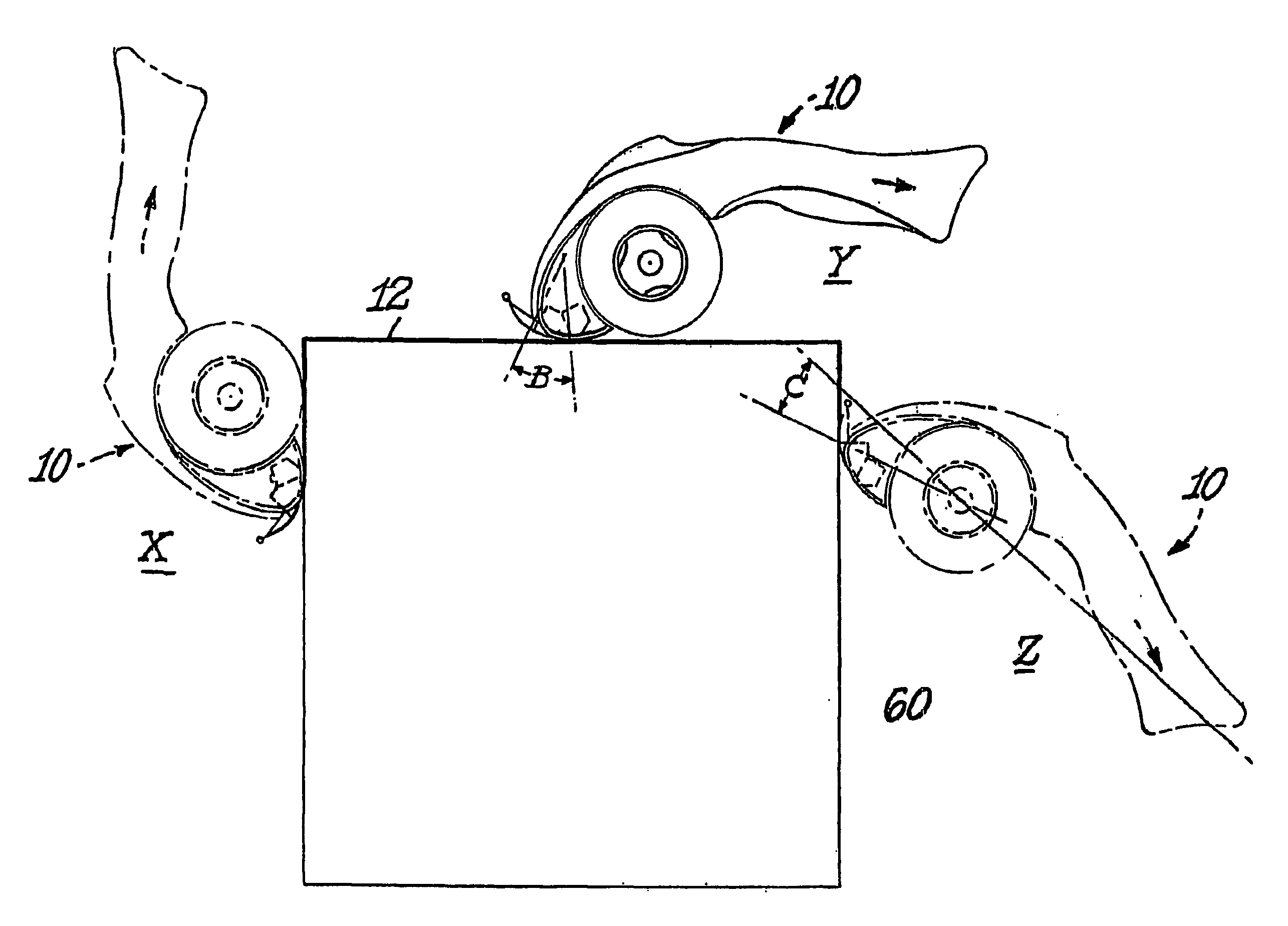
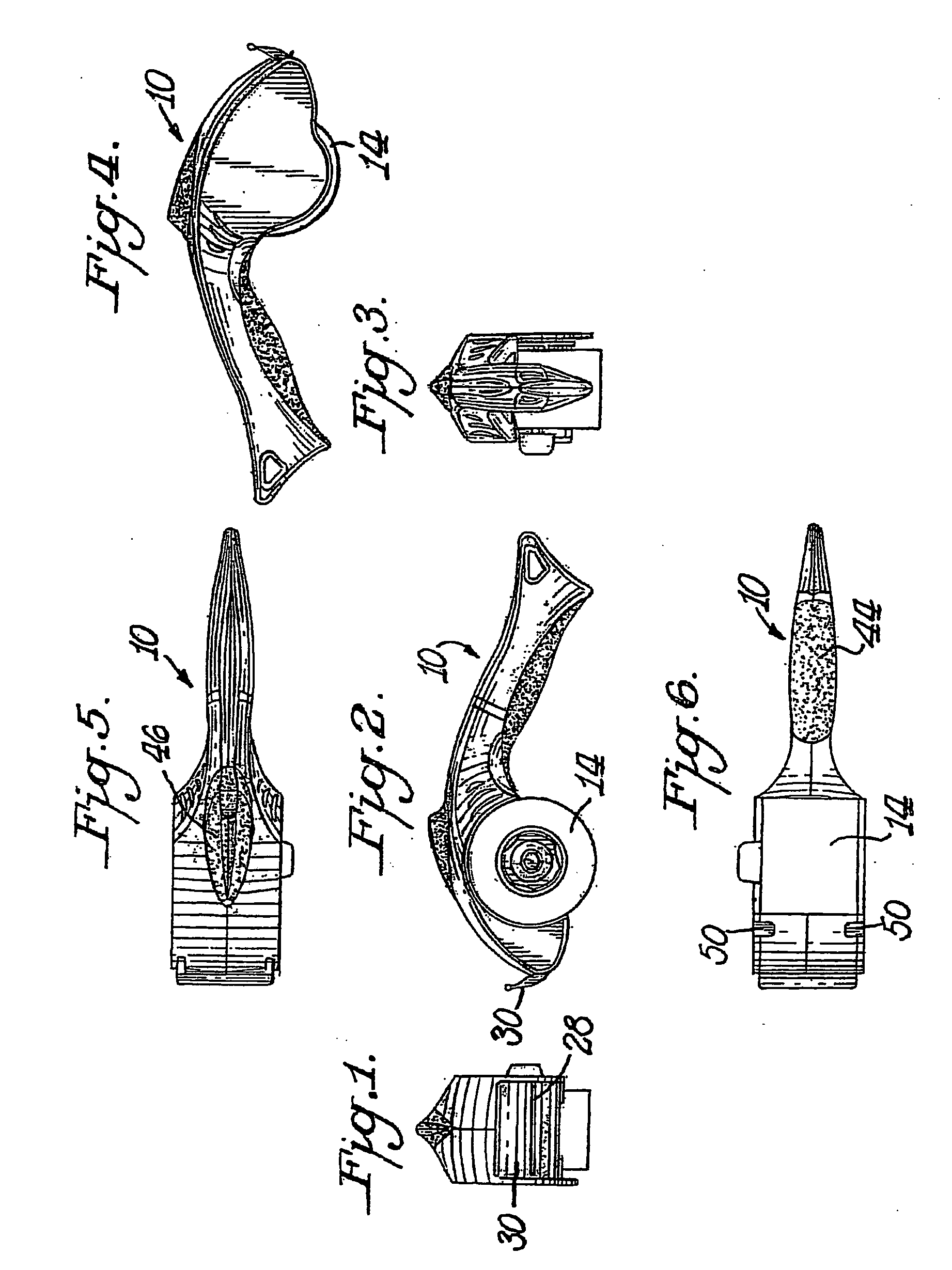
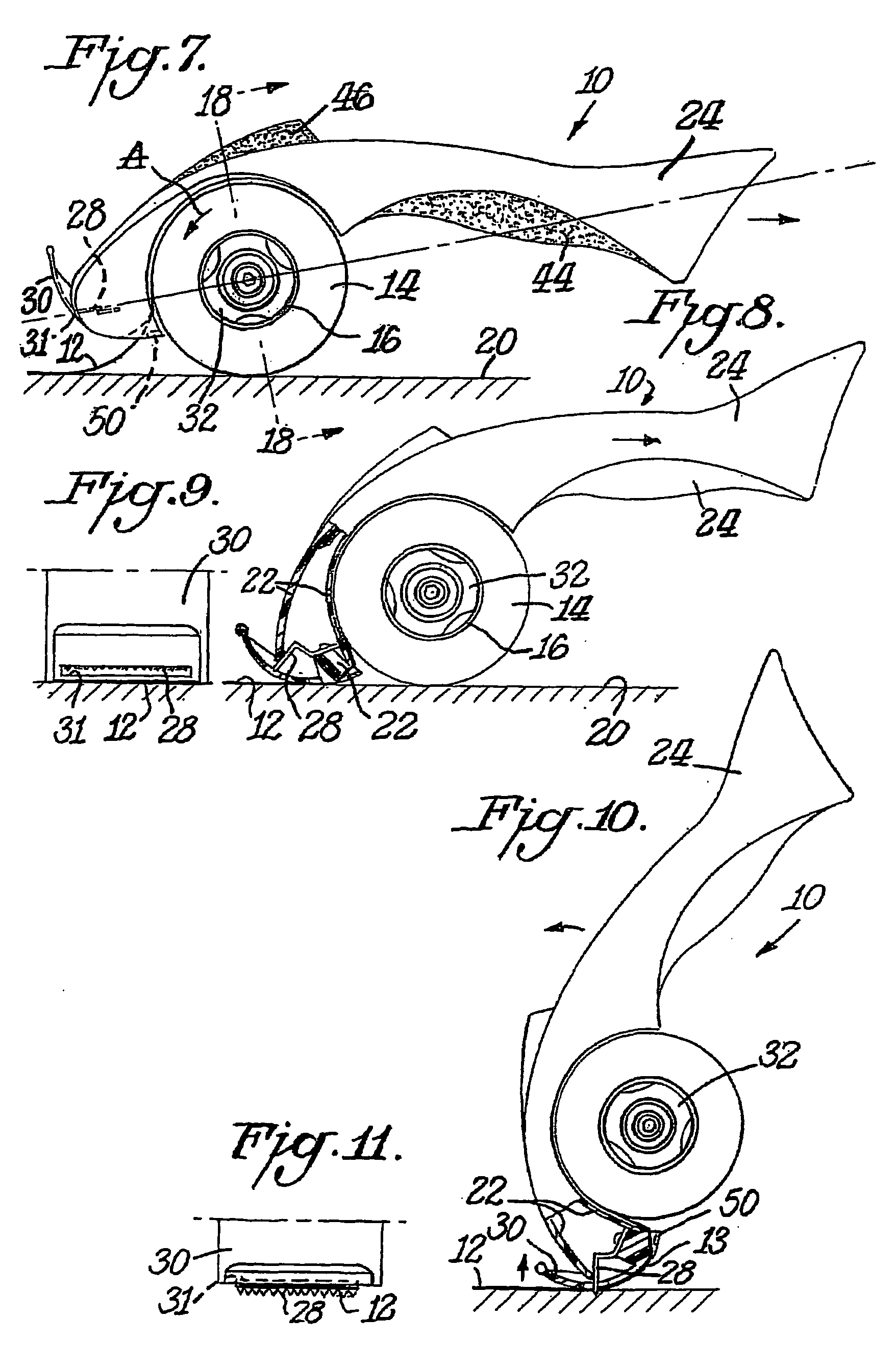
[0039]The adhesive film dispenser 10 is configured for ergonomic application of adhesive film or tape 12 from a roll 14 onto an application surface 20 (See FIGS. 7, 8 and 21). The tape 12 is typically wound around a cardboard core 16 in a well known manner. The dispenser 10 is particularly useful in dispensing tape 12 wound on a 1½ inch core versus the more typical core size of 3 inches used in most pistol grip dispensers such as those described above. The smaller core size enhances the ergonomic features of adhesive film dispenser 10. The reduced core size enables a lower profile dispenser where the roll 14 skims surface 20 during application of the tape (See FIGS. 9 and 21). By mounting the tape roll 14 in line with the dispenser handle, rather than atop the handle as was done in the prior art, application of tape is eased.

[0040]The dispenser 10 is formed around an underlying frame 22 (See. FIG. 8) and generally comprises a handle 24 at one end of the frame 22, a mandrel 26 in the...


PUM

PropertyMeasurementUnit
angleaaaaaaaaaa
angleaaaaaaaaaa
sizeaaaaaaaaaa

Abstract

An ergonomic dispenser of a roll of adhesive film facilitates application of that film to a surface with minimum manipulation by the user. The dispenser has a low profile where the cutting blade, axis of rotation of the adhesive film roll and dispenser handle lie in closely aligned planes. This creates a low profile dispenser which places the roll of adhesive film in close proximity to the application surface. A flexible shield overlies the cutting blade to prevent unwanted user contact with the blade. Various means are used to manage the loose end of film after it is cut off the roll so that it does not adhere to the roll or double over on itself. Unidirectional movement of the roll is also used to manage the loose end of tape after cutoff. Optionally, blade means may be added to the dispenser's handle for use in opening cartons, cutting string or the like.

Description

CROSS-REFERENCE TO RELATED APPLICATIONS[0001]This application is a continuation of prior U.S. patent application Ser. No. 10 / 454,000 filed Jun. 4, 2003 the benefit of which is claimed pursuant to 35 U.S.C. §120.BACKGROUND OF THE INVENTION[0002]Numerous types of adhesive film dispensers are currently in use ranging from relatively simple single use dispensers as shown in Corbo, et al., U.S. Pat. No. 4,961,525 to devices used by bulk mailers of packages such as Clements U.S. Pat. No. 6,296,033.[0003]The latter category of dispenser is characterized by a pistol grip handle having a bulky roll of tape above it and a dispensing mechanism, including cutting blade, jutting out at about 90° or greater from a plane which passes through the handle and centerline of the tape. This type of dispenser features a triangular orientation of tape, handle and cutting blade. Other examples of such “pistol grip” adhesive film dispensers are described in U.S. Pat. Nos. 6,491,082; 6,478,067; 6,296,033; 6,...

Claims


Application Information

Patent Timeline
Patent Type & Authority Applications(United States)
IPC IPC(8): B32B37/10B65H35/00
CPCB65H35/0033Y10T156/1795Y10T156/1365Y10T156/18Y10T156/1788Y10T156/12Y10T156/1793
Inventor WOJTKUN, THOMASDAUNTER, DOMINICTHIMM, DAVIDBAILEY, CURTHAWLEY, JAMESVULPITTA, BRIAN
Owner SHURTECH BRANDS
Why Eureka
Try Eureka