
Photocatalyst-coated body and photocatalytic coating liquid therefor

a photocatalyst and coating liquid technology, applied in the direction of catalyst activation/preparation, organic compound/hydride/coordination complex catalyst, physical/chemical process catalyst, etc., can solve the problems of organic material decomposition or deterioration, and achieve the effect of preventing corrosion of a substrate, superior weather resistance, and noxious gas decomposability

Active Publication Date: 2008-10-16
TOTO LTD
View PDF10 Cites 18 Cited by
  • Summary
  • Abstract
  • Description
  • Claims
  • Application Information

AI Technical Summary

Benefits of technology

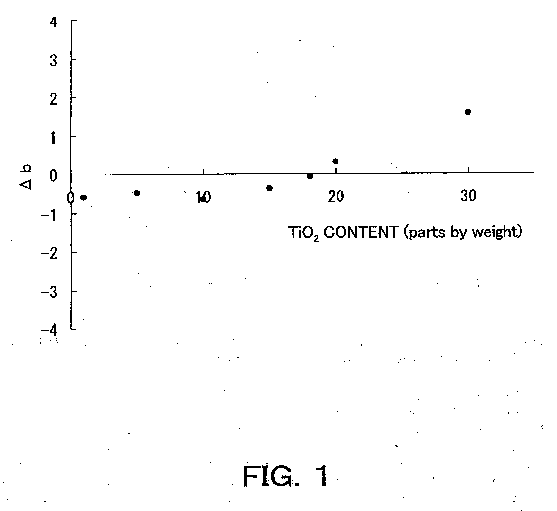
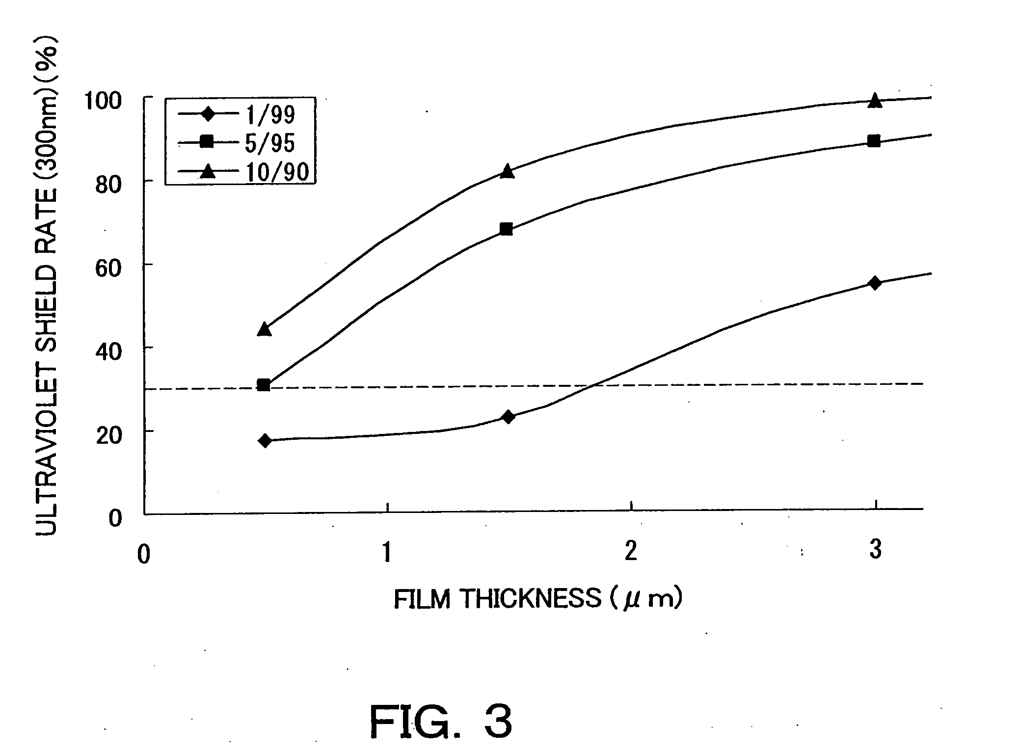
[0007]The inventors have currently found that a photocatalyst-coated body which is superior in weather resistance, noxious gas decomposability, and various coating properties (such as ultraviolet absorptivity, transparency and film strength) can be obtained while preventing corrosion of a substrate (in particular an organic substrate), by constituting a photocatalyst layer with a specified composition that comprises photocatalyst particles and inorganic oxide particles in a specified mass ratio and minimizing a hydrolyzable silicone and a surfactant to no or a small amount.
[0008]Accordingly, it is an object of the present invention to provide a photocatalyst-coated body which is superior in weather resistance, noxious gas decomposability, and various coating properties (such as ultraviolet absorptivity, transparency and film strength) while preventing corrosion of a substrate (in particular an organic substrate). It is also an object of the present invention to provide a photocatalyst coating liquid for the photocatalyst-coated body.

Problems solved by technology

In the meantime, a problem has been conventionally known that, when a substrate for a photocatalyst layer is composed of an organic material, the organic material is decomposed or deteriorated due to photocatalytic activity of the photocatalyst.

Method used


Image

  • Photocatalyst-coated body and photocatalytic coating liquid therefor
  • Photocatalyst-coated body and photocatalytic coating liquid therefor
  • Photocatalyst-coated body and photocatalytic coating liquid therefor

Examples


examples

[0038]The present invention will be described in detail with reference to the following Examples, but the present invention is not limited to these Examples.

[0039]The raw materials used to produce a photocatalyst coating liquid in the following Examples will be described below.

Photocatalyst Particles

[0040]Titania aqueous dispersion (average particle diameter: 30 nm to 60 nm, basic)

Inorganic Oxide Particles

[0041]Aqueous dispersion-type colloidal silica (produced by Nissan Chemical Industrials Ltd., trade name: SNOWTEX 50, particle diameter: 20 nm to 30 nm, solids content: 48%) (used in Examples 1 to 19 and Examples 24 to 27)

[0042]Aqueous dispersion-type colloidal silica (produced by Nissan Chemical Industrials Ltd., trade name: SNOWTEX 40, particle diameter: 10 nm to 20 nm, solids content: 40%) (used in Example 20)

[0043]Aqueous dispersion-type colloidal silica (produced by Nissan Chemical Industrials Ltd., trade name: SNOWTEX 50, particle diameter: 20 nm to 30 nm, solids content: 48%...

examples 1-7

Evaluation of Weather Resistance

[0049]A photocatalyst-coated body having a photocatalyst layer was produced as follows. A colored organic coated body was prepared as a substrate. The colored organic coated body was obtained by coating a float plate glass with a general-purposed acrylic silicone with a carbon black powder added, and then sufficiently drying and curing it. On the other hand, a photocatalyst coating liquid was prepared by mixing a titania aqueous dispersion as a photocatalyst, an aqueous dispersion-type colloidal silica as an inorganic oxide, water as a solvent, and a polyether-modified silicone surfactant all together in the proportions shown in Table 1. It should be noted that the photocatalyst coating liquid does not include the hydrolyzable silicone. The total solid concentration of the photocatalyst and the inorganic oxide in the photocatalyst coating liquid was 5.5% by mass.

[0050]The photocatalyst coating liquid thus obtained was applied, by spray coating, to the...

examples 8-11

Evaluation of Noxious Gas Decomposability

[0053]A photocatalyst-coated body having a photocatalyst layer was produced as follows. A colored organic coated body was prepared as a substrate. The colored organic coated body was obtained by coating a float plate glass with a general-purposed acrylic silicone with carbon black powder added, and then sufficiently drying and curing it. On the other hand, a photocatalyst coating liquid was prepared by mixing a titania aqueous dispersion as a photocatalyst, an aqueous dispersion-type colloidal silica as an inorganic oxide, water as a solvent, a polyether-modified silicone surfactant, and a polycondensate of tetramethoxysilane as a hydrolyzable silicone all together in the proportions shown in Table 2. It should be noted that the photocatalyst coating liquids in Examples 8 and 10 do not include the hydrolyzable silicone. The total solid concentration of the photocatalyst and the inorganic oxide in the photocatalyst coating liquid was 5.5% by m...


PUM

PropertyMeasurementUnit
Fractionaaaaaaaaaa
Fractionaaaaaaaaaa
Fractionaaaaaaaaaa

Abstract

There is disclosed a photocatalyst-coated body which is superior in weather resistance, noxious gas decomposability, and various coating properties (such as ultraviolet absorptivity, transparency and film strength) while preventing corrosion of a substrate (in particular an organic substrate), and a photocatalyst coating liquid therefor. The photocatalyst-coated body comprises a substrate and a photocatalyst layer provided on the substrate. The photocatalyst layer comprises photocatalyst particles of 1 part or more by mass and less than 20 parts by mass; inorganic oxide particles of 70 parts or more by mass and less than 99 parts by mass; and a hydrolyzable silicone of zero parts or more by mass and less than 10 parts by mass, provided that a total amount of the photocatalyst particles, the inorganic oxide particles and the hydrolyzable silicone is 100 parts by mass.

Description

TECHNICAL FIELD[0001]The present invention relates to a photocatalyst-coated body which is superior in weather resistance, noxious gas decomposability, and various coating properties, particularly suitable for use in exterior materials for buildings and the like. The present invention also relates to a photocatalyst coating liquid for the photocatalyst-coated body.BACKGROUND ART[0002]Photocatalysts such as titanium oxide have been recently utilized in various applications such as exterior materials for buildings. Employment of the photocatalyst makes it possible to harness light energy to decompose various types of noxious substances and to hydrophilize the surface of a substrate coated with the photocatalyst to allow a stain deposited on the surface to be easily washed away with water. The following techniques have been known for producing photocatalyst-coated bodies coated with such a photocatalyst.[0003]It is known to use an aqueous dispersion comprising photocatalytic metallic o...

Claims


Application Information

Patent Timeline
IPC IPC(8): B01J21/06C09D7/61
CPCB01J35/004C09D183/04B01J37/0219C03C17/007C03C2217/45C03C2217/475C03C2217/477C03C2217/478C03C2217/48C03C2217/71C08K3/22C09D1/00C09D7/1216C09D7/1266B01J37/0009C09D7/61C09D7/67B01J35/39C09D5/00
Inventor KITAZAKI, SATORUKAMESHIMA, JUNJIOMOSHIKI, KOJITAKAKI, YOJITANAKA, YUKIIWATA, HIRONAGAHAYAKAWA, MAKOTOKANNO, MITSUYOSHI
Owner TOTO LTD
Learn More