
Semiconductor light engine using polymer light pipes and lighting systems constructed with the light engine

a technology of semiconductor light sources and light engines, applied in the field of light engines, can solve the problems of difficult design and construction of lighting systems employing semiconductor light sources, difficult cost effective manufacture and assembly of these lighting systems, and difficulty in developing a cost effective system, and achieve the effect of easy assembly

Active Publication Date: 2008-10-16
MAGNA INTERNATIONAL INC
View PDF7 Cites 89 Cited by
  • Summary
  • Abstract
  • Description
  • Claims
  • Application Information

AI Technical Summary

Benefits of technology

The present invention provides a light engine and automotive lighting system that use semiconductor light sources, such as LEDs. The light engine includes a heat sink, positioning member, and light pipes to capture and transfer the light emitted from the semiconductor light sources. The light pipes are securely positioned using slots in the positioning member and a retaining member to bias them. The light engine is easy to assemble and can be used in automotive lighting systems. The technical effects of the invention include improved efficiency, reduced size, and improved thermal management.

Problems solved by technology

However, lighting systems employing semiconductor light sources have proven to be difficult to design and construct as, even with the most advanced semiconductor light sources, multiple sources typically must be employed to obtain the necessary light output levels.
Further, as a lighting system may include many semiconductor light sources and their corresponding light pipes, the cost effective manufacture and assembly of these lighting systems has been challenging.
In particular, developing a cost effective system for positioning the light pipes, which system is operable over the wide range of thermal environmental operating conditions which an automotive system must meet, has proven to be difficult.

Method used


Image

  • Semiconductor light engine using polymer light pipes and lighting systems constructed with the light engine
  • Semiconductor light engine using polymer light pipes and lighting systems constructed with the light engine
  • Semiconductor light engine using polymer light pipes and lighting systems constructed with the light engine

Examples


Embodiment Construction

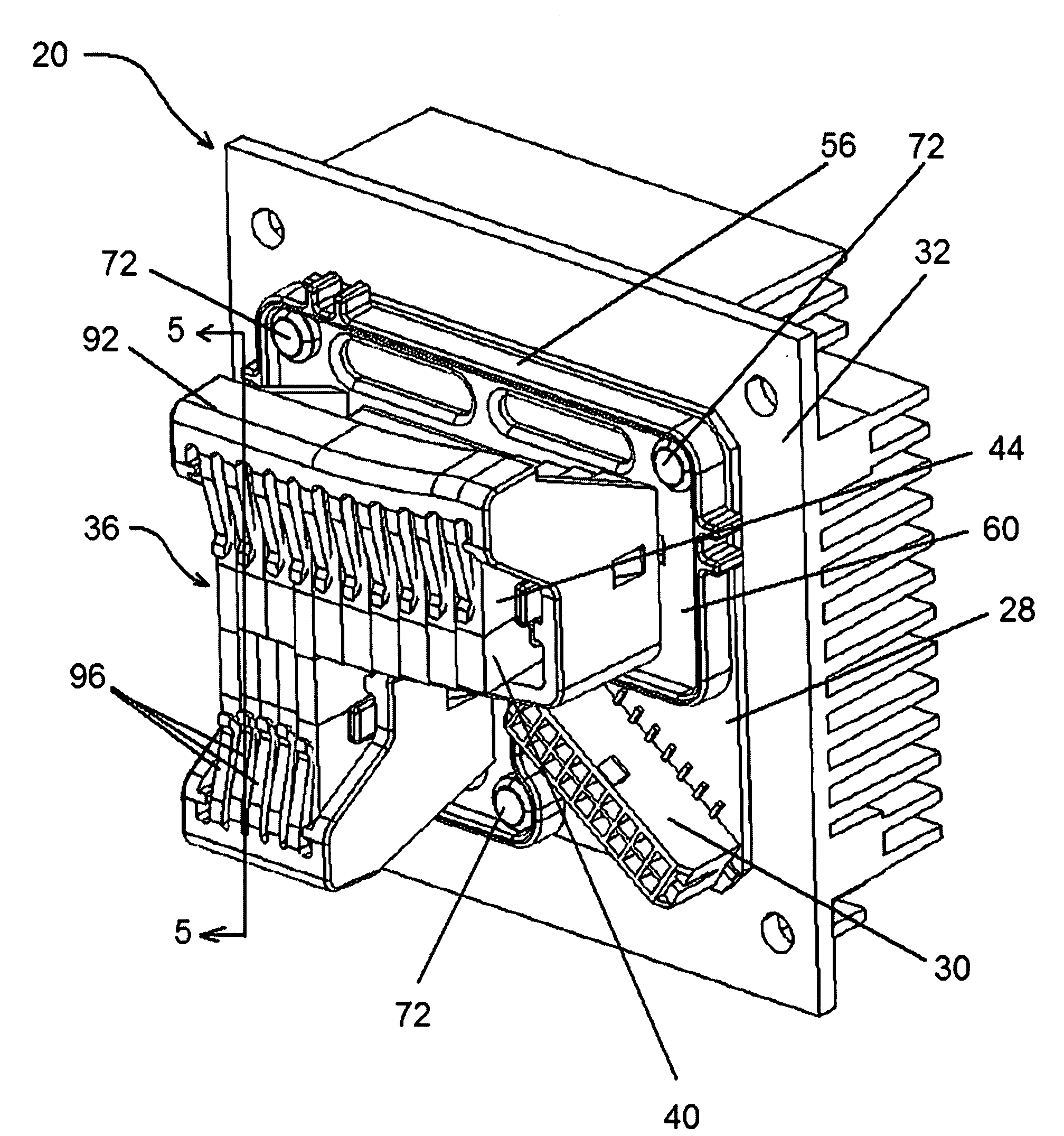
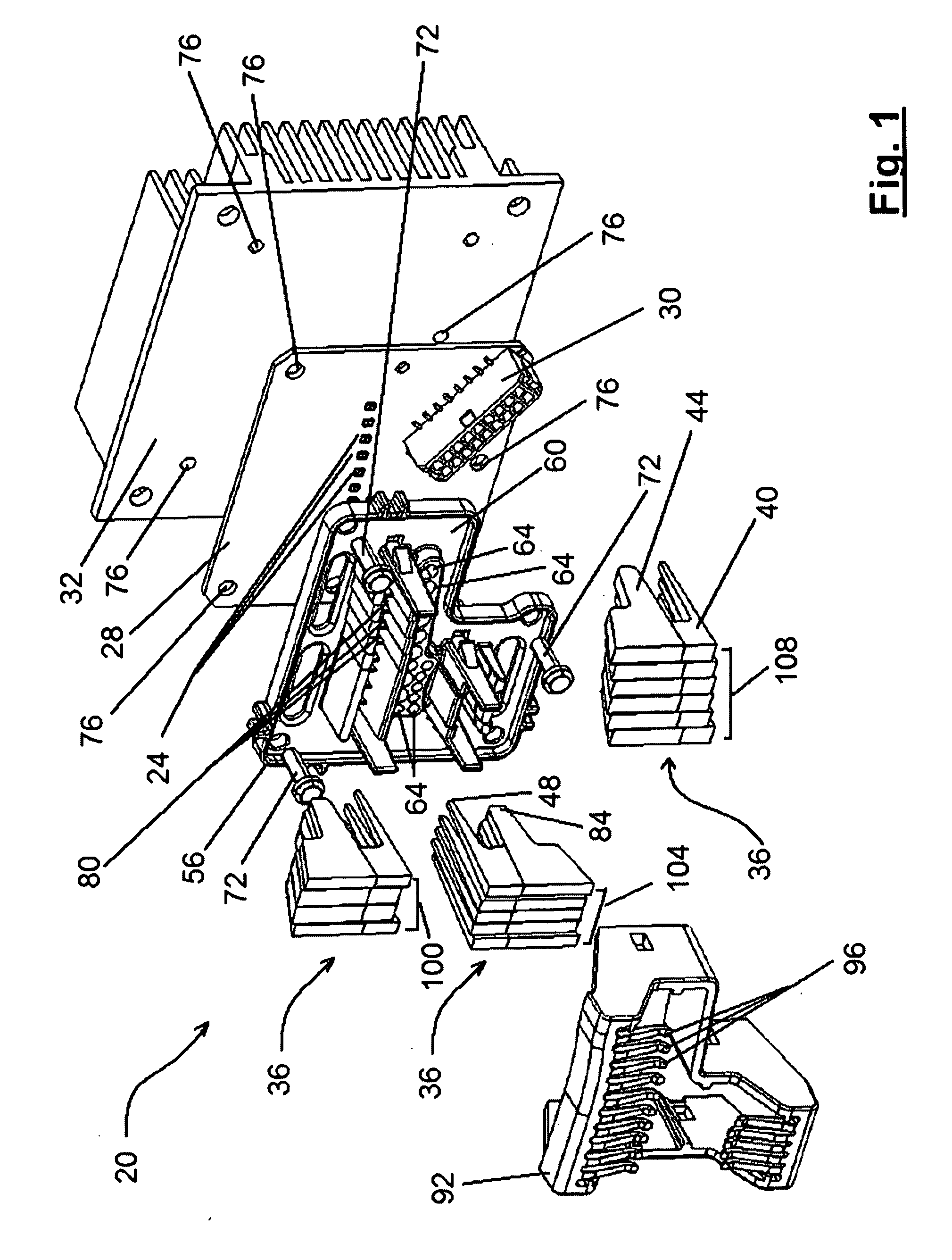
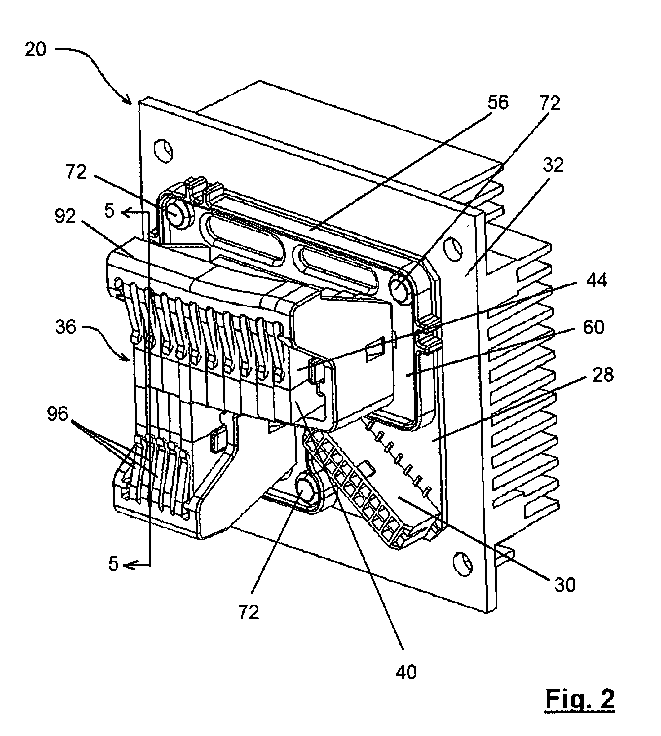
[0017]A light engine in accordance with the present invention is indicated generally at 20 in FIGS. 1 and 2. As will be apparent to those of skill in the art, one or more light engines 20 can be combined with an optics system, such as a lens or set of lenses, and an enclosure to form automotive lighting systems, such as headlamps, etc.

[0018]Light engine 20 includes a set of semiconductor light sources, which in this embodiment are LEDs 24, which emit the light provided by light engine 20. LEDs 24 are mounted on a substrate 28, which can be an electrical circuit board or other suitable mounting element. Preferably, substrate 28 includes the necessary electrical circuit connectors to supply power to LEDs 24 from an appropriate connector 30 or other power source.

[0019]As is known to those of skill in the art, the expected operating lifetime of LEDs is dependent upon the operating temperature of their semiconductor junction and it is thus important that heat be effectively removed from ...


PUM


Abstract

A light engine for use in systems such as automotive lighting systems employs two or more semiconductor light sources, such as LEDs. Light emitted from the light sources is captured by light pipes which are mounted such that the light capturing surface of the light pipes are properly positioned, with respect to the semiconductor light sources, substantially independent of changes in the dimensions of the light pipes which may result from thermal expansion or contraction of the light pipes. The light pipes transfer substantially all of the light captured from the semiconductor light sources to light emitting surfaces of the light pipes which can be appropriately located adjacent the output optics of the lighting system. The light engine can be easily assembled as the light pipes are retained in slots on a positioning member which is mounted at a known position with respect to the semiconductor light sources.

Description

FIELD OF THE INVENTION[0001]The present invention relates to a light engine employing semiconductor light sources to produce light. More specifically, the present invention relates to a light engine comprising a plurality of semiconductor light sources each of whose emitted light is transferred from the semiconductor source to a respective desired destination via a respective light pipe and to a lighting system constructed with the light engine.BACKGROUND OF THE INVENTION[0002]With the development of semiconductor light sources, such as light emitting diodes (LEDs), which can output relatively high levels of white light, the development of automotive lighting systems, such as headlamp fixtures, which employ such semiconductor light sources has become possible. However, lighting systems employing semiconductor light sources have proven to be difficult to design and construct as, even with the most advanced semiconductor light sources, multiple sources typically must be employed to ob...

Claims


Application Information

Patent Timeline
Patent Type & Authority Applications(United States)
IPC IPC(8): B60Q1/00B60Q1/26B60Q1/04
CPCB60Q1/0041F21S48/1154F21S48/1208F21S48/1241F21Y2101/02G02B6/0001F21Y2115/10F21S41/143F21S41/151F21S41/24F21S41/29F21S41/663
Inventor DOLSON, MICHEAL D.WOODWARD, RONALD O.MCFADDEN, JAMES R.
Owner MAGNA INTERNATIONAL INC
Learn More