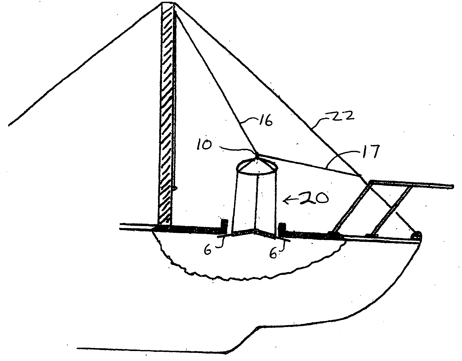
[0006]The subject invention relates to a unique three-sided wind scoop for capturing the wind and directing a flow of the
fresh air down into the interior of a sailboat, e.g. its enclosed cabin, through an open hatch to improve the ventilation and atmospheric conditions, e.g. temperature, humidity, etc. therein. In addition to its basic purpose the wind scoop of the present invention provides numerous other advantages. For instance, it is very simple to manufacture, requiring essentially only sewing and / or heat sealing of the fabric materials involved; it is easily installable and readily maintainable in a stationary working position, as well as, being easily collapsible and storable in a small bag or pouch within the confines of the said sailboat. Indeed the pouch could be as small as about 1 foot by 2 feet. The wind scoop of this invention may also be employed without having to detach the hatch cover, as well as without having to
drill, screw or nail any holes in the sailboat, since the open hatch cover does not interfere with the use of the three-sided wind scoop. Thus the hatch cover needs only to be opened in its conventional manner and remain so during the use of the three-sided wind scoop. Further the unique three-sided wind scoop of this invention provides more surface area for capturing the wind and thus provides more air for better ventilation of the cabin and this
advantage is coupled with the fact that the wind scoop of this invention is capable of capturing the wind for said ventilation regardless of the direction of an anchored sailboat with respect to the wind. Thus regardless of whether the wind changes direction when the sailboat is anchored or the anchored boat itself changes direction with regard to the wind, the three-sided wind scoop of this invention will self-automatically continue to capture the wind and direct its
airflow down into the cabin of the anchored sailboat.
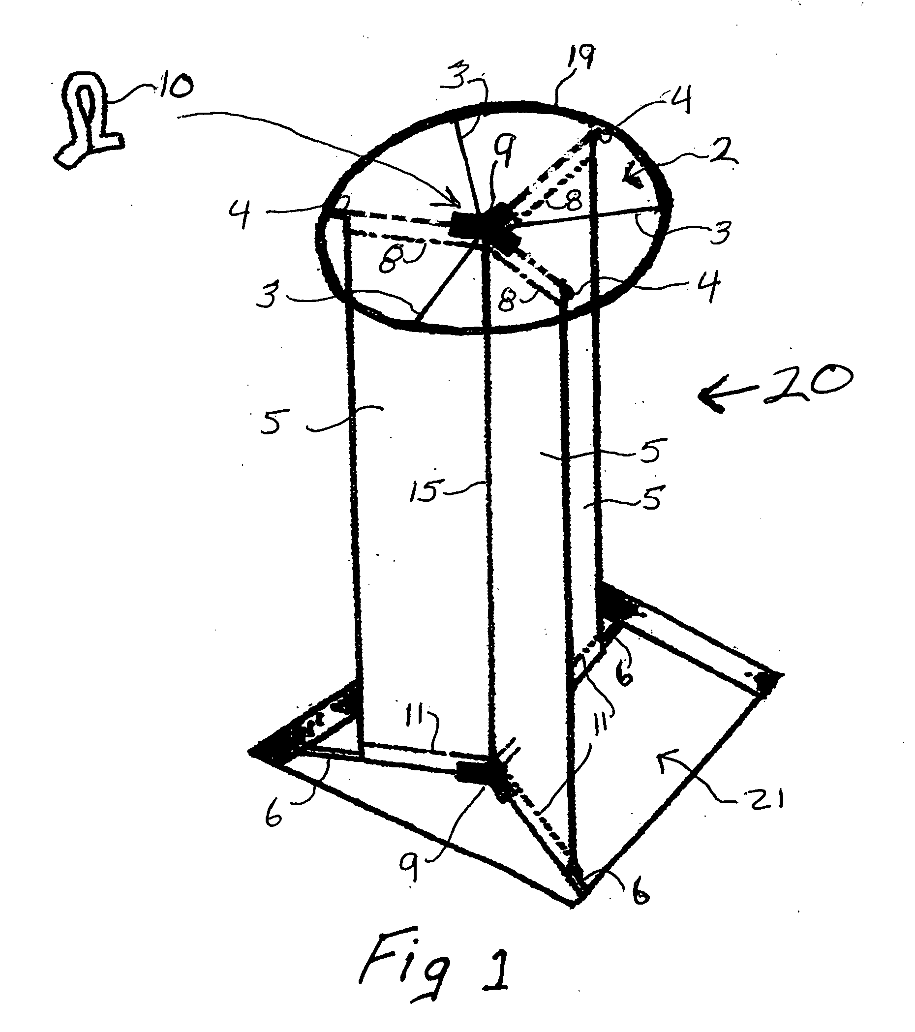
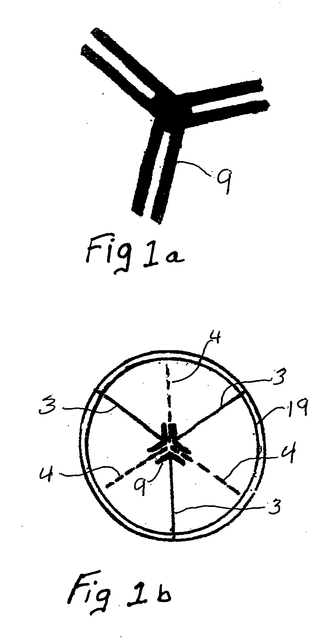
[0007]Accordingly the three-sided wind scoop of this invention comprises three flexible rectangular-shaped fabric panels, one side of each panel being joined together to form a center seam; the top each said three panels being attached in an equal (about 120 degree) angle Y-shaped configuration to an essentially circular flexible fabric which forms a cap or top cover (hereinafter referred to as “cap”) for said three-sided wind scoop. While the Y-shaped configured panels of the wind scoop are designed to capture the wind and direct the flow of air down into the boat regardless of the direction of the wind in relation to the boat, the cap of the wind scoop is designed to capture the wind flowing upward from said Y-shaped configured panels and redirect it back downward, thereby adding to and facilitating the downward flow of the air.
[0008]The cap of the present wind scoop of this invention comprises an essentially circular flexible fabric having three flexible battens permanently encased in the cap by sewing or heat sealing them into the top or bottom surface of the cap, each flexible
batten running from the outer edge of the cap to about the center of the cap, and three sleeves or pockets, (hereinafter referred to as “sleeves”) each being provided to hold a rigid
batten. In addition the outer edge of the cap may be supported in any conventional manner to help maintain the shape of the cap. There is also an equal (about 120 degree) angle Y-tube connector at about the center of the cap for
insertion of one end of each of the rigid battens so as to help hold them in place. The sleeves for these three rigid battens each run from about the outer edge of the cap to said equal angel Y-tube connector and along about the same lines as that of the above mentioned three rectangular shaped panels attached to said cap, while each flexible
batten runs along a line that is about half-way between two adjacent rigid batten lines. The cap also has a means, e.g. a strap, hook or loop (hereinafter referred as a “strap”) at the general center of the cap for fixing the wind scoop to a support line so that the wind scoop can be adjusted and maintained in an upright position over the open hatch of the sailboat. While said strap may be made from any suitable material, preferably it is made from the same fabric as that of the cap and it is positioned around about the center of said Y-tube connector by sewing the ends of the strap to the cap.
[0009]Finally, a sleeve or pocket (hereinafter referred to as a “sleeve”) is provided along the bottom of each of said Y-shaped configured rectangular panels, each sleeve being designed to hold a rigid batten for
insertion at one end into a second equal (about 120 degree) angle Y-tube connector at the general central meeting point at the bottom of said Y-shaped configured rectangular panels. Moreover, this second set of rigid battens at the bottom of said Y-shaped configured rectangular panels is such that an exposed portion of the other end of each batten can abut up against the
deck of the boat adjacent to the bottom opening of the hatch and thereby secure the bottom of the wind scoop upright and inside the hatch opening when in use.
[0011]Said sleeves for the rigid battens of the cap may be positioned on the top or underside surface of the cap by sewing or heat sealing a part of the panels to themselves or by using a strip of additional fabric in any conventional manner. More preferably the sleeves for the rigid battens are on the underside of the cap and not only run along the lines of the top edge of the rectangular panels attached to the cap, they are a part of said panel attachment itself. Likewise the sleeves for the rigid battens along the bottom edge of the three panels of the three sided wind scoop may be made by heat sealing or sewing a part of the panels to themselves or by sewing an additional strip of fabric to the panels. It is preferred to merely fold a strip of fabric around the bottom edge of each panel and sew each side of the fabric to the panel to form such bottom sleeves. Such sleeves for all the rigid battens employed in the wind scoop are preferably only large enough to snugly fit and maintain the battens therein and long enough to fit over the ends of the equal angle Y-tube connectors employed. It is preferred that any additional fabric employed to prepare the wind scoop used to form the sleeves of the rigid battens be the same as the fabric used for the cap and panels of the wind scoop. The flexible and rigid battens provide strength and stability to the cap during use of the three-sided wind scoop.
