
Snag-resistant sinker line shield

a sinker line and shield technology, applied in fishing, other angling devices, animal husbandry, etc., can solve the problems of sinker line chafing, broken fishing line, and loss of the tackle elements attached thereto, and achieve the effect of preventing chafing of the sinker lin

Inactive Publication Date: 2008-10-16
BRASSEUR BERNARD P
View PDF99 Cites 7 Cited by
  • Summary
  • Abstract
  • Description
  • Claims
  • Application Information

AI Technical Summary

Benefits of technology

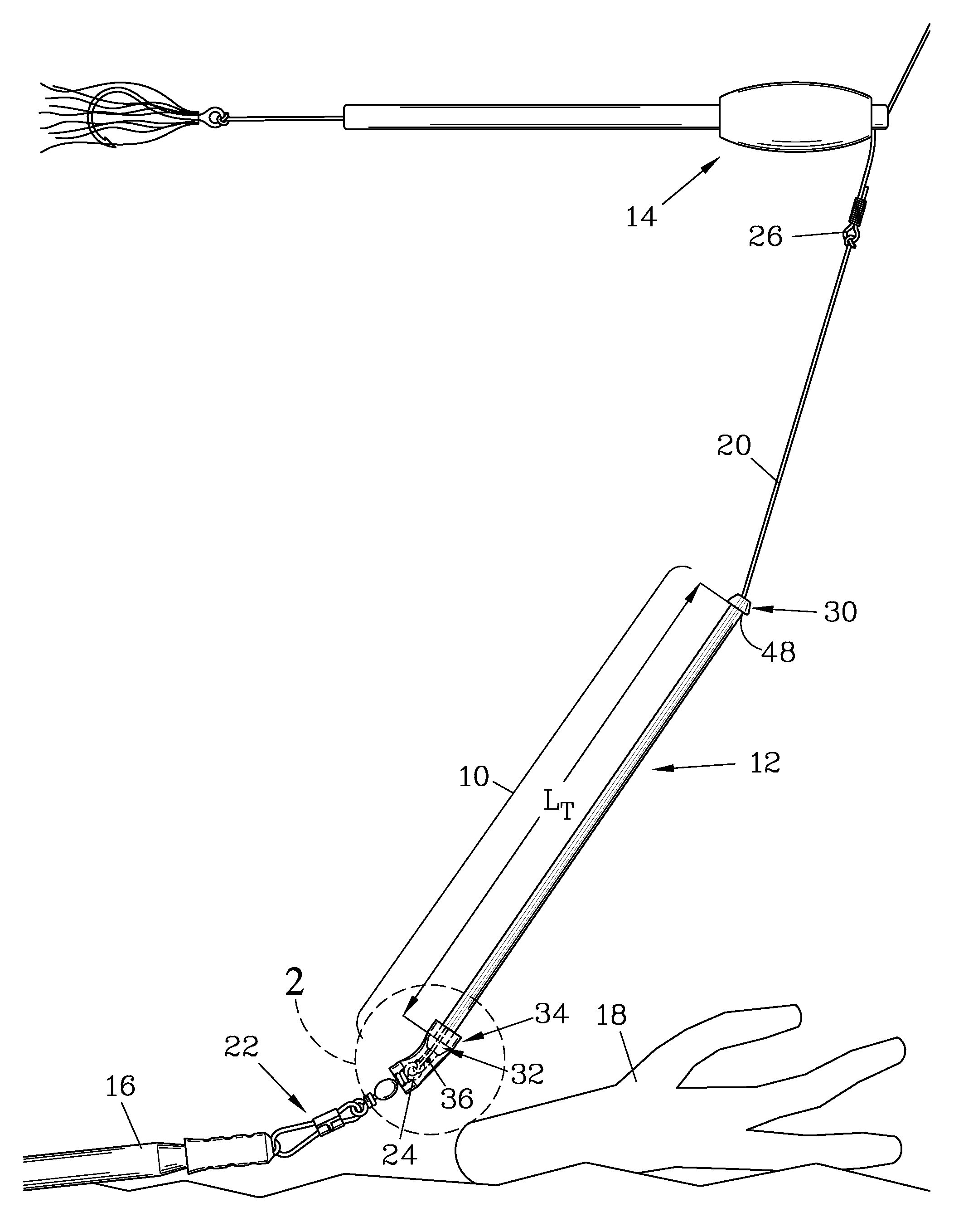
[0009]The present invention provides a line shield for use with a sinker line which is attached to a sinker. The sinker serves to maintain a fishing lure or bait in the vicinity of the bottom of a body of water, and the line shield complements the sinker and acts as a deflector to help guide the sinker over any submerged obstructions. The line shield also prevents chafing of the sinker line as it is drawn past and over submerged objects. The line shield is well suited for use with a bait locating device such as taught in U.S. Pat. No. 5,555,668, but can provide advantages when used in other fishing situations as well.
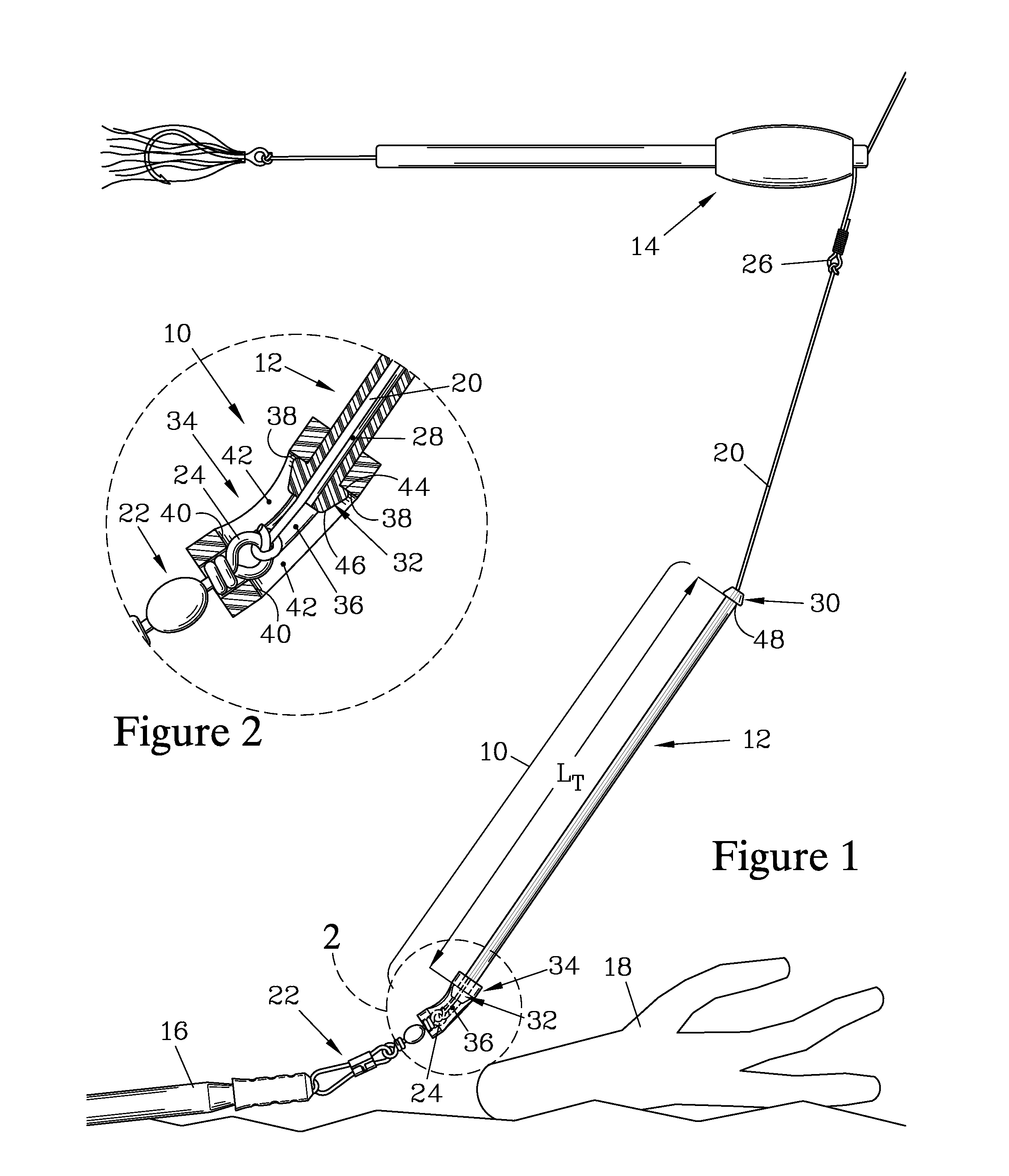
[0011]To allow the resilient tube to act as a deflector for the sinker, the line shield has means for securing the tube with respect to the sinker. Frequently, the sinker line is tied to an eye associated with the sinker, either an eye provided directly on the sinker or an eye on a connecting element such as a snap which in turn attaches to the sinker. In such cases, means for securing the tube with respect to the sinker are preferably provided by a hood of resilient material having a hood passage therethrough, where the hood passage is configured to frictionally engage the eye and the tube trailing end, when the tube trailing end is inserted into the hood passage. The tube trailing end can be enlarged to provide a more positive engagement with the hood passage.
[0012]The resilient hood serves to maintain the tube in close proximity to the sinker or the connecting element; thus, when the tube leading end is raised by a float or by tension on the sinker line, the tube acts as a ramp-shaped deflector to help guide the sinker over obstructions.
[0014]Preferably, the tube has a length of at least about three inches. The tube is preferably formed from a slightly flexible material, allowing it to provide a bouncing effect to the sinker to further reduce snagging. It is also preferred for the tube to be formed of a transparent or translucent material such as plastic to reduce its visibility when submerged.
[0015]The tube trailing end is preferably enlarged so as to form a trailing end ledge, facing toward the tube leading end, and a tapered guide surface, facing away from the tube leading end. When the tube trailing end is formed with a trailing end ledge, the hood passage forcibly engages the trailing end ledge to maintain the resilient hood engaged with the tube, while the tapered guide surface facilitates insertion of the tube trailing end into the hood passage.
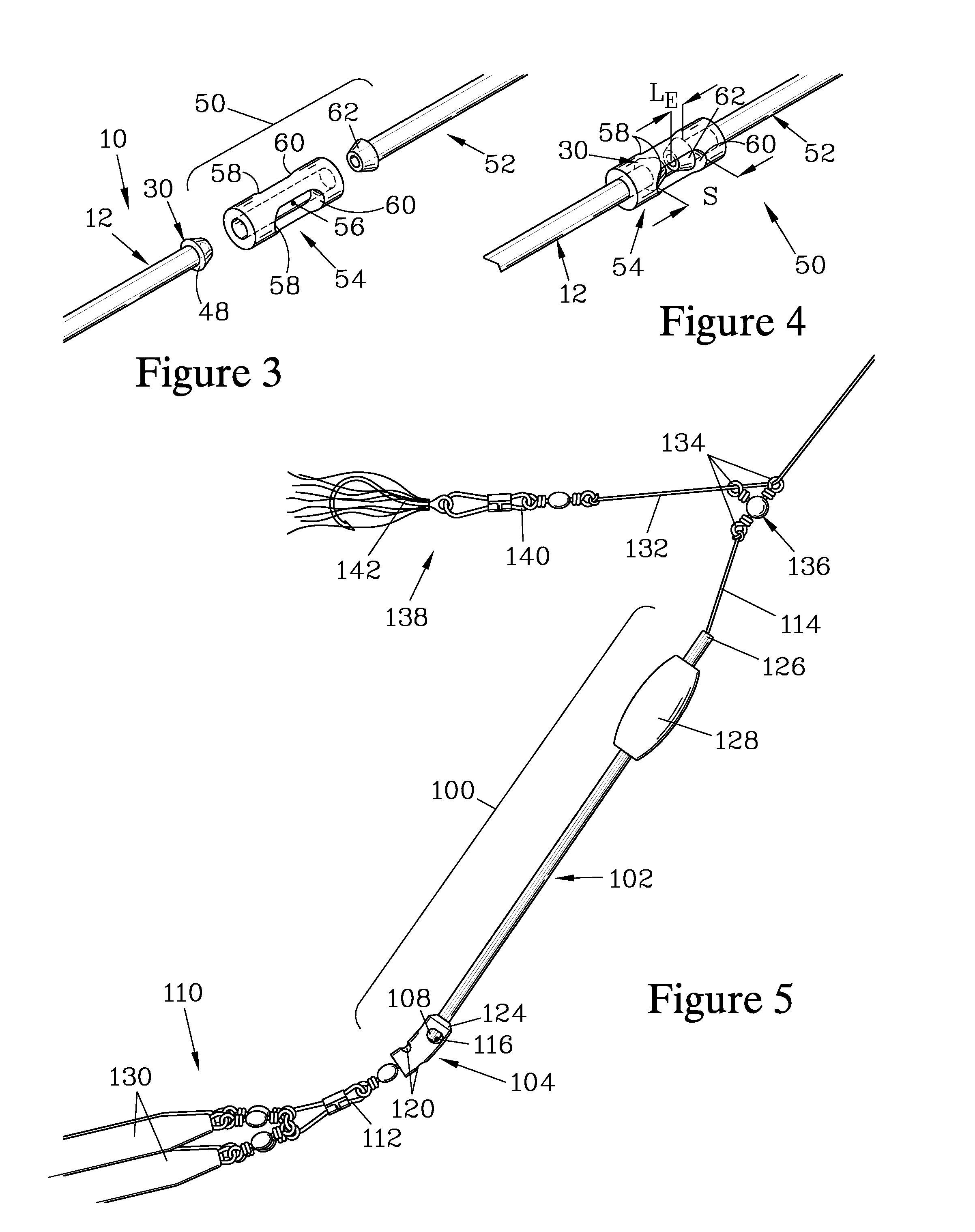
[0016]The resilient hood preferably has at least one cutout that communicates with the hood passage, which aids in providing a more positive engagement of the trailing end ledge of the tube. Preferably, the at least one cutout is so configured as to also positively engage the eye of the sinker or connector element. In another embodiment, at least one pair of opposed cutouts is provided. Preferably, the resilient hood has a hood leading end that is tapered to further resist snagging.

Problems solved by technology

These tackle elements are attached to a fishing line and, when used in close proximity to the bottom of a body of water, these elements have been found prone to snagging on weeds, rocks, submerged branches, and similar obstacles.
This snagging frequently results in breakage of the fishing line and loss of the tackle elements attached thereto.
Breakage of the line due to snagging also requires the user to attach new tackle, taking time away from actively fishing.
The sinker which rests on the bottom may still become snagged on obstruction; however, when the sinker line is selected to be weaker than the fishing line that attaches to the lure, then the sinker line can be broken if the sinker becomes snagged, and the lure can then be recovered.
The '435 device lacks the ability to adjust the height of the lure in the manner provided by the '668 bait locating device.
Furthermore, when the buoyant member is designed to break apart, it may be susceptible to damage by abrasion.
While the above devices address the problem of snagging and loss of lures and hooks, they do not overcome the problem of sinkers becoming snagged.
However, the reduction in overall effective weight due to the buoyant portion and the tendency to stand upright when the sinker line is tensioned may limit the useful applications of the sinker.
However, the weight may still be prone to snagging in situations where there is insufficient space to accommodate the twisting motion, and may be prone to entanglement in weeds.
Again, the use of a buoyant portion will tend to reduce the overall effectiveness of the sinker.
Additionally, the buoyancy of these elongated sinkers would not appear to be sufficient to allow the sinkers to maintain their upright position when expopsed to sidways forces, and thus they may not be able to maintain the lure at a desired height over the bottom when trolling and / or when used in areas with a strong current.
The upright position of these sinkers may increase the likelihood of the sinker falling into crevices and becoming snagged therein.
While the wire legs of the '030 patent may provide a benefit in rocky environments, they would appear to increase the risk of snagging when employed in areas with weeds and / or branches, and may increase the risk of entanglement with the lure or bait when casting.
Again, the sinker may be prone to snagging when used in areas with weeds and / or branches.

Method used


Image

  • Snag-resistant sinker line shield
  • Snag-resistant sinker line shield
  • Snag-resistant sinker line shield

Examples


Embodiment Construction

[0029]The present invention provides a line shield for a sinker line that attaches to a sinker, the line shield helping to prevent snagging of the sinker on underwater obstructions. FIGS. 1-2 illustrate one embodiment of the present invention, a line shield 10 having a resilient tube 12. FIG. 1 shows the line shield 10 when employed with a bait locating device 14, such as that taught in U.S. Pat. No. 5,555,668, incorporated herein by reference, and a sinker 16. The sinker 16 illustrated in FIG. 1 is a linkable sinker discussed in copending application Ser. No. 11 / 828,417 of the present inventor entitled “Snag-Resistant Linkable Sinker”. The line shield 10 acts as a deflector to guide the sinker 16 and any associated connector elements over obstructions such as rocks, weeds, or branches, such as a branch 18 also shown in FIG. 1. The sinker 16 is shown attached to a sinker line 20 by a snap swivel 22 having a swivel eye 24 to which the sinker line 20 is tied. The sinker line 20 in tur...


PUM


Abstract

A line shield has a tube that can be secured with respect to a sinker to guide the sinker over submerged obstructions. The tube has a tube passage, through which a line attached to the sinker passes, and terminates at a tube leading end and a tube trailing end. The tube is preferably secured to the sinker by a resilient hood having a hood passage sized to frictionally fit over the tube trailing end, and to frictionally fit over an eye of the sinker or a connecting element attached thereto, such as a snap. The frictional engagement of the resilient hood with the eye and the tube trailing end maintains the tube in close proximity to the sinker or connecting element. In use, the tube leading end is raised so that the tube acts as a ramp-shaped deflector to guide the sinker over obstructions.

Description

FIELD OF THE INVENTION[0001]The present invention relates to sinker systems employed to hold a fishing line near the bottom of a body of water, and more particularly to a line shield which can be employed with sinkers to greatly reduce the tendency of the sinkers to snag or become entangled by obstructions or weeds.BACKGROUND OF THE INVENTION[0002]To catch fish by angling, a number of fishing tackle elements are employed such as hooks, lures, sinkers, etc. These tackle elements are attached to a fishing line and, when used in close proximity to the bottom of a body of water, these elements have been found prone to snagging on weeds, rocks, submerged branches, and similar obstacles. This snagging frequently results in breakage of the fishing line and loss of the tackle elements attached thereto. Breakage of the line due to snagging also requires the user to attach new tackle, taking time away from actively fishing.[0003]U.S. Pat. No. 5,555,668 of the present inventor teaches a bait l...

Claims


Application Information

Patent Timeline
Patent Type & Authority Applications(United States)
IPC IPC(8): A01K95/00A01K91/06
CPCA01K91/08A01K95/00
Inventor BRASSEUR, BERNARD P.
Owner BRASSEUR BERNARD P
Learn More