
Dual Size Tool-Bit Holder

a tool-bit and holder technology, applied in the direction of chucks, manufacturing tools, mechanical equipment, etc., can solve the problems of only being able to accommodate a single cross-sectional size tool, requiring extensive operator involvement, and changing a tool-bit takes tim

Active Publication Date: 2008-10-09
INSTY BIT
View PDF36 Cites 40 Cited by
  • Summary
  • Abstract
  • Description
  • Claims
  • Application Information

AI Technical Summary

Benefits of technology

[0007]A tool-bit holder for varying tool-bit shank profiles, the tool-bit holder comprising a hub having a longitudinal bore adapted for receiving a tool-bit shank. The longitudinal bore comprises a first section having a first profile and a first length, and a smaller second section having a second profile and second length. The hub has a plurality of radial slots communicating with the longitudinal bore. A collar is fixedly attached to the hub and disposed annularly about the hub and forms a channel over each radial slot. A sleeve is axially slidably mounted along the hub....

Problems solved by technology

However, changing a tool-bit takes time and extensive operator involvement.
Previous quick-release systems are only able to accommodate a single cross-sectional size tool-bit shank.

Method used


Image

  • Dual Size Tool-Bit Holder
  • Dual Size Tool-Bit Holder
  • Dual Size Tool-Bit Holder

Examples


Embodiment Construction

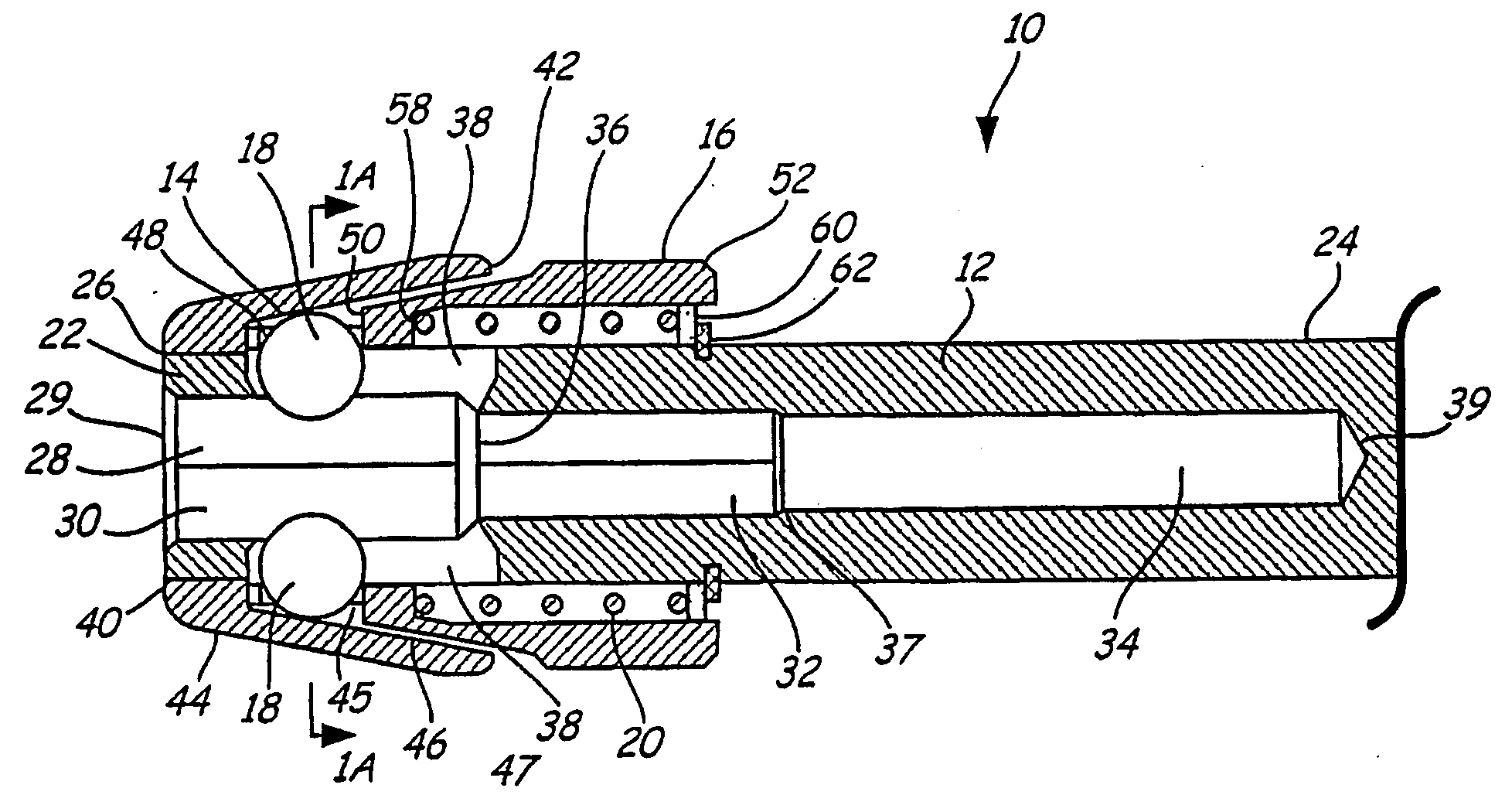
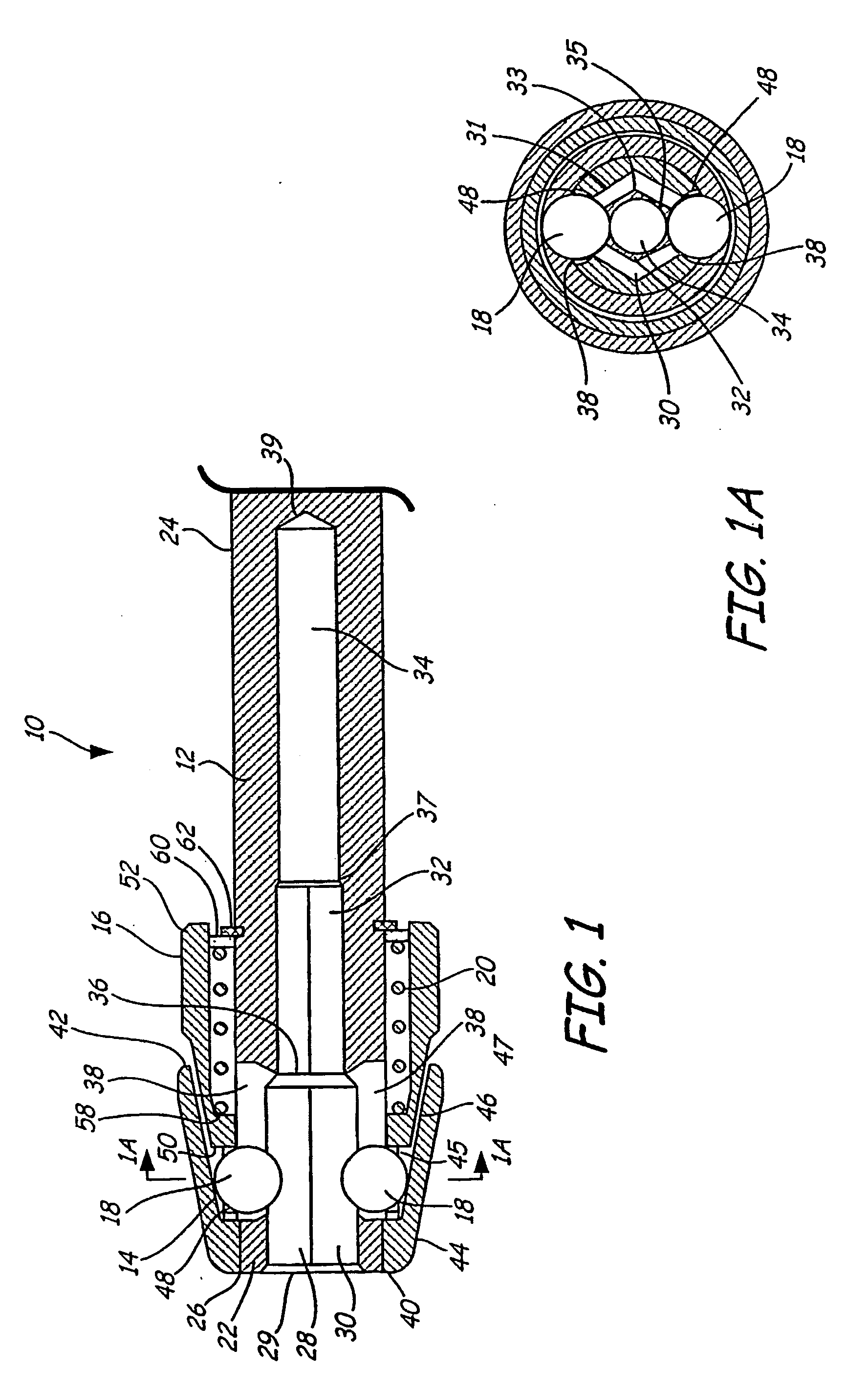
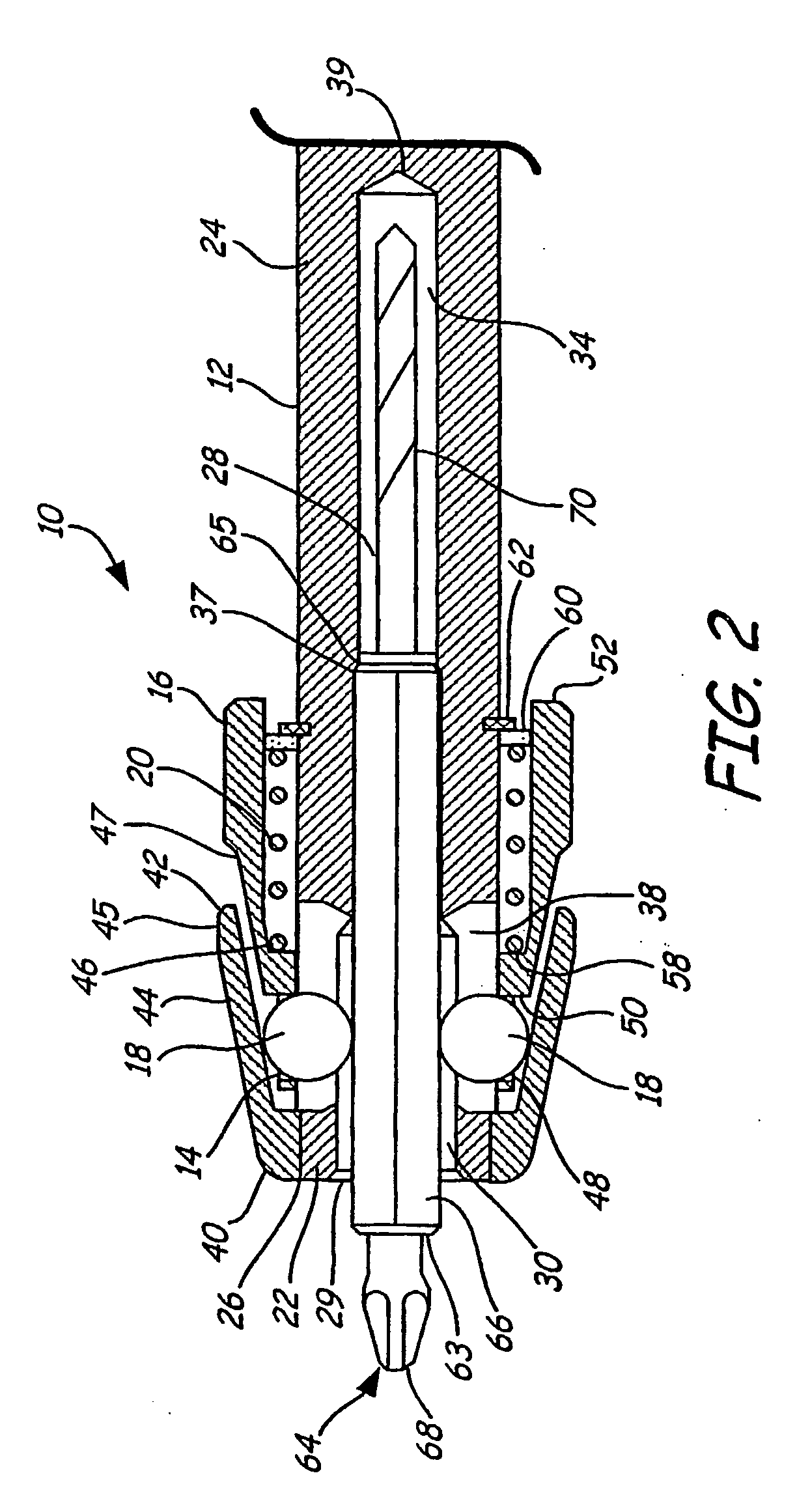
[0017]The present invention is a tool-bit holder for capturing and retaining a tool-bit that has a quick release mechanism. A first embodiment of an automatic tool-bit holder is shown in FIG. 1. The tool-bit holder 10 includes a hub 12, a collar 14, a sleeve 16, detent balls 18 and a spring 20. FIG. 1A is a cross-sectional view taken along line 1A of FIG. 1.

[0018]The hub 12 has a forward distal end 22, ending in a forward face 26, and a rear proximal end 24. Preferably, the proximal end 24 of the hub 12 is shaped to provide a connection to a chuck for a power tool. Alternatively, the proximal end 24 is a spindle that provides a connection to other devices such as tools used for drilling and driving. The proximal end 24 typically has a hexagonally-shaped cross-section.

[0019]A longitudinal bore 28 extends perpendicularly into the forward face 26 and axially toward the proximal end 24 of the hub 12. The longitudinal bore comprises a first bore section 30, which has an open end 29. The ...


PUM


Abstract

A tool-bit holder (10) for varying tool-bit shank profiles comprising a hub (12) having a longitudinal bore (28) adapted for receiving a tool-bit shank (66, 70, 80). The hub (12) has a plurality of radial slots (38) communicating with the first section (30) of the longitudinal bore (28). The tool-bit holder (10) has a collar (14) fixedly attached to the hub (12) adjacent the open (29) and disposed annularly about the hub (12). A sleeve (16) is axially slideably mounted and disposed annularly about the hub (12). The sleeve (16) has a plurality of radial bores (48), each being in communication with a respective radial slot (38) of the hub (12) with a detent ball (18) disposed within each. A spring (20) is provided for biasing the sleeve (16) towards the open end (29) wherein the detent ball (18) engages an inner ramp face (46) of the collar (14).

Description

BACKGROUND OF THE INVENTION[0001]This invention relates to chuck assemblies for tool-bits, and more particularly, to a quick release chuck adapted to receive and retain a plurality of tool-bits having varying shank cross-sectional sizes.[0002]Tool-bits include tools used for drilling and driving fastener devices such as screws, nuts and bolts, and other work elements requiring rotational motion. The traditional or “incremental” design typically consists of a mechanism that houses three adjustable jaws which protrude at an angle into a bore. An external sleeve is coupled to the jaws via internal gear teeth. When a tool shank is inserted into the bore, the sleeve is rotated by a user. As the sleeve is rotated in one direction, the jaws are forced towards the center of the bore to clamp a tool-bit and tighten the sleeve into place (e.g. using a chuck key). When the sleeve is rotated in the opposite direction, the jaws are opened. This chuck style is able to accommodate a variety of too...

Claims


Application Information

Patent Timeline
IPC IPC(8): B23B31/12B23B31/107B25B21/00B25B23/00
CPCB23B31/1071B25B21/007B25B23/0035Y10S279/905B23B31/22Y10T279/17786B23B2231/38Y10T279/17145Y10T279/17743Y10T279/17811Y10T279/17752B23B2231/0232
Inventor WIENHOLD, JAMES L.
Owner INSTY BIT
Learn More