Louver blade positioning device of motorized shutter assembly

a technology of motorized shutters and positioning devices, which is applied in the direction of building components, constructions, buildings, etc., can solve the problems of unsatisfactory manual closure, several sets of motorized shutters may encounter an angular variance,

Inactive Publication Date: 2008-10-09
NIEN MADE ENTERPRISE CO LTD
View PDF5 Cites 23 Cited by
  • Summary
  • Abstract
  • Description
  • Claims
  • Application Information

AI Technical Summary

Benefits of technology

[0005]The object of the present invention is to provide a louver blade positioning device of a motorized shutter assembly, such that the louver blades can be effectively positioned at a specific angle, for example, full-closed or at a specific angle as desired.

Problems solved by technology

Consequently, this causes the disadvantage of unsatisfactory manual closure.
Moreover, during motorized operations, several sets of motorized shutters may encounter an angular variance under the same control command possibly due to the clearance among the elements.

Method used


Image

  • Louver blade positioning device of motorized shutter assembly
  • Louver blade positioning device of motorized shutter assembly
  • Louver blade positioning device of motorized shutter assembly

Examples


first embodiment

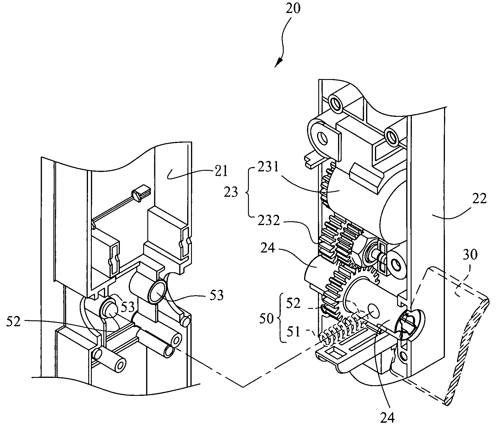
[0021]As shown in FIG. 2 to FIG. 4B, they are schematic views illustrating the structure of a resilient member of a louver blade positioning device of a motorized shutter assembly according to the present invention. A motorized module 10 of a shutter assembly 11 includes a first housing 21 and a second housing 22 coupled together, housing a transmission mechanism 23, including a motor 231 and a gear 232, as well as a driving shaft 24 therein. In conjunction with the driving shaft 24, a louver blade 30 is driven to rotate. The motor 231 is a direct current, an alternating current or a stepper motor capable of reversible motions, such that the louver blade 30 rotates forward or backward accordingly. The transmission mechanism 23, usually having a torque limiter or a clutch means (not shown in the drawing), facilitates the manual operations and rotations of the louver blade 30, without damaging the motor 231 or the transmission mechanism 23.

[0022]To adjust and restore the louver blade ...

second embodiment

[0027]FIG. 6A is a view illustrating a resilient member made according to the present invention. The elastic element 51 of the resilient member 50 in the shape of a spring and the inserted element 52 integrated in the form of a protrusion on the spring respectively replace the spring and bearing ball in the previous embodiments. The spring is fixed on the first housing 21 at two ends thereof, to support the deformation under the operation of an external force as shown in FIG. 6A, thereby producing a force F0.

[0028]FIG. 6B and FIG. 6C are schematic views illustrating the function of a resilient member made according to the second embodiment of the present invention. In FIG. 6B, the protrusion on the spring exactly fits into the indented positioning portion 41 of the driving shaft 24. Given the force F0 acted upon by the protrusion perpendicular to the center of rotation of the driving shaft 24, the driving shaft 24 is maintained at a steady state as soon as it rotates to a specific a...


PUM


Abstract

A louver blade positioning device of a motorized shutter assembly includes an indented positioning portion or a protruded portion formed upon a driving shaft and a resilient member coming into contact with the driving shaft and the indented positioning portion or the protruded portion in a radically movable manner at a fixed angle. When the louver blades are rotated to approach a specific angle, the resilient member moves into the indented positioning portion or the protruded portion. Through the resilient force exerted by the resilient member on the indented positioning portion or the protruded portion, the driving shaft rotates to approach the specific angle, such that the louver blades become positioned at the specific angle when being rotated to approach the specific angle, thereby becoming free from the angular clearance inherent among transmission components of the motorized shutter assembly.

Description

BACKGROUND OF THE INVENTION[0001]1. Field of the Invention The present invention relates to a device for a motorized shutter assembly, particularly a louver blade positioning device of a motorized shutter assembly.[0002]2. Description of the Prior Art[0003]Referring to FIG. 1A, a conventional motorized shutter assembly 11 primarily includes a plurality of louver blades 13 and a push rod 12 driven by a motorized module 10 in order to drive the plurality of louver blades 13 in linkages and to adjust an angle of louver blades in a motorized manner through a remote control 101.[0004]Referring to FIG. 1B, the motorized module 10 includes a motor 102 and a transmission mechanism 103 to drive in reversible movement of the louver blades 13 through a driving shaft 104. In addition to motorized operations, ordinary motorized shutter assembly can be manually operated by pushing the push rod 12 in order to adjust an angle of louver blades as shown in FIGS. 1C and 1D. However, when one manually ...

Claims


Application Information

Patent Timeline
Patent Type & Authority Applications(United States)
IPC IPC(8): E06B7/096
CPCE06B7/096
Inventor HUANG, HORNG TSANNLIN, CHING HWA
Owner NIEN MADE ENTERPRISE CO LTD
Why Eureka
Try Eureka