Nail

a technology of nailing and splinting, which is applied in the direction of rail fasteners, mechanical devices, and ways, etc., can solve the problems of inability to use planking and waste of operators' time, and achieve the effect of saving time and labor, and preventing the surface of a planking from being damaged

Inactive Publication Date: 2008-10-02
CHANNG CHIN IND CORP
View PDF22 Cites 5 Cited by
  • Summary
  • Abstract
  • Description
  • Claims
  • Application Information

AI Technical Summary

Benefits of technology

[0009]An objective of the present invention is to provide a nail that can prevent from damaging the surface of a planking while pulling out the nail and save the time and labor.
[0010]Accordingly, the nail of the present invention comprises a head, a shank connected to the head, and a series of umbrella-shaped threads spirally connecting to the shank, wherein the head has a recess formed on the upper surface thereof, the free end of the shank forms a nail end, and the umbrella-shaped threads are extended from the nail end to the head. By abovementioned structure, the nail can be successfully nailed into the planking and directly rotated back from the planking by a tool, and then without prying the nail by any crowbar, the surface of the planking can be prevented from damaging, and thus the time and labor can be efficiently saved. Besides, the planking can be used repeatedly after the nail is pulled out and the resources waste can be highly reduced.

Problems solved by technology

While in operating, the conventional nail has following shortcomings:1. Due to the reason that the nail 1 has to be nailed back first by the tool, and then pried by the crowbar, it is surely inconvenient and wasting time for the operators; besides, the way to pry the nail by the crowbar is not only labor consuming but easy to damage the surface of the planking, and which causes the planking to be unable to use repeatedly and the resource waste.2. Due to the reason the conventional nail 1 includes the threads 13 close to the head 11 and merely spirally formed on the shank 12, which means said threads 13 are not spirally formed on the whole shank 12, the threads 13 formed by the upper cutting edge 132 and bottom cutting edge 133 will cause the obstacle during the process of nailing, which lead to the result that the conventional nail 1 has to be pulled out by rotating back via the tool and prying via the crowbar.

Method used


Image

  • Nail
  • Nail
  • Nail

Examples


Embodiment Construction

[0017]Before the present invention is described in greater detail, it should be noted that the like elements are denoted by the same reference numerals throughout the disclosure.

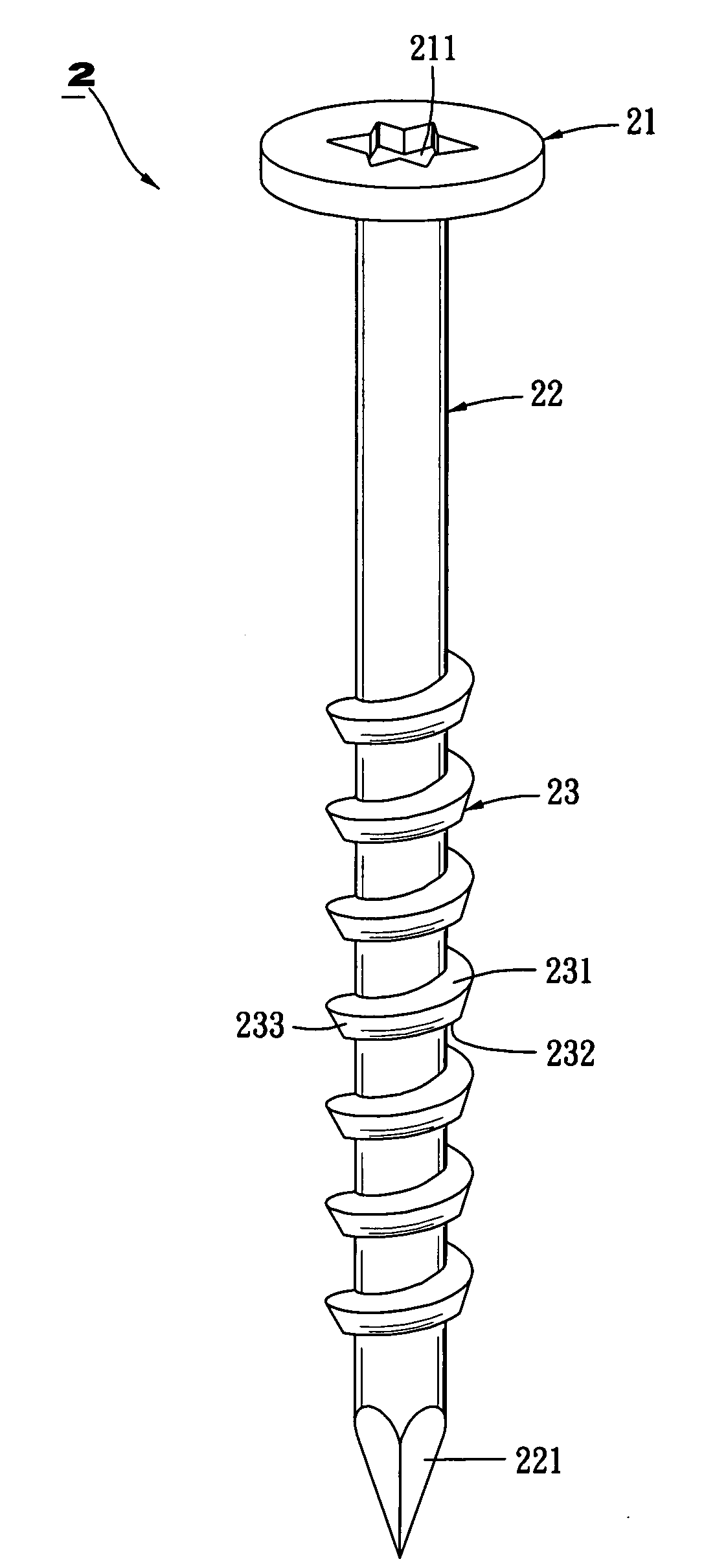
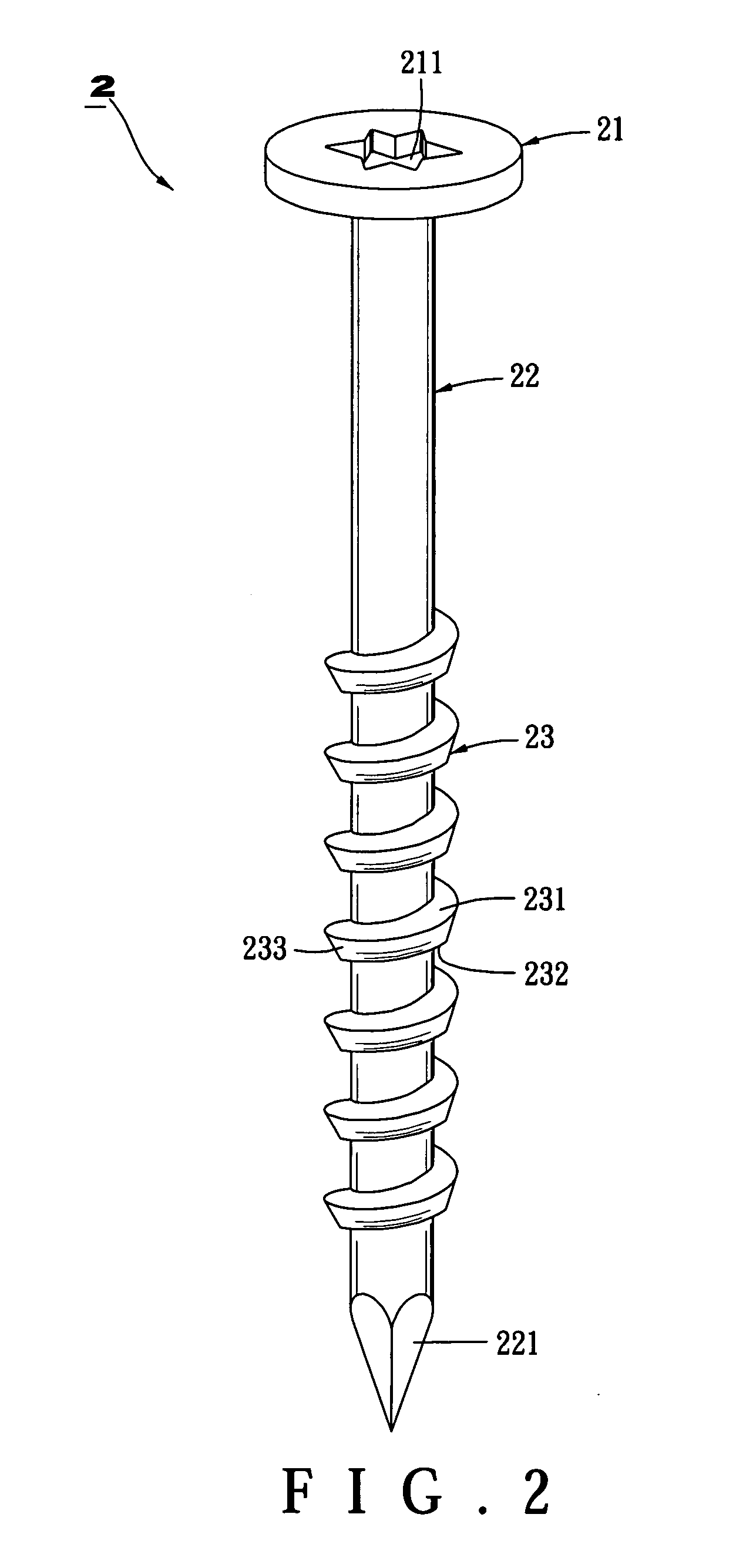
[0018]Referring to FIG. 2, a nail 2 in accordance with a preferred embodiment of the present invention comprises a head 21, a shank 22 connecting to the head 21, and a series of umbrella-shaped threads 23 spirally formed on the shank 22. The head 21 has a recess 211 formed on the upper surface thereof, wherein a tool (such as a pneumatic tool) inserts into the recess 211 to rotate the head 21. The recess 211 can be Torx, Slotted, Squared, and it is Torx in the present embodiment. Besides, the shank 22 has a nail end 221 defined on a free end thereof, and the serial umbrella-shaped threads 23 are extended from the nail end 221 to the head 21; wherein, said threads include a top face 231 toward the head 21, an end edge face 232 opposite to the top face 231, and a peripheral face 233 connecting the top face 231...


PUM


Abstract

A nail comprises a plurality of umbrella-shaped threads spirally formed on the shank and extended from the nail end to the head, wherein the umbrella-shaped thread includes a top face and an end edge face, in which the outer diameter of the top face is greater than the outer diameter of the end edge face, such that the nail can be nailed into a planking easily and successfully without the obstacle of the umbrella-shaped threads. While pulling out the nail, an actuating tool is used directly to rotate back the nail, so as to prevent from damaging the surface of the planking and efficiently save the time and labor.

Description

BACKGROUND OF THE INVENTION[0001]1. Field of the Invention[0002]The present invention generally relates to a fastener, and in particular a nail that can prevent from damaging the surface of the planking and save the time and labor while in operating.[0003]2. Description of the Related Art[0004]Referring to FIG. 1, a conventional nail comprises a head 11 with an recess 111 formed on the upper surface of the head 11, a shank 12 connected to the head 11 and defining a nail end 121 at a free end of the shank 12, a thread 13 spirally formed on the shank 12 closed to the head 11, a plurality of cutting grooves 131 formed on the threads 13 to section the threads 13.[0005]While using, a knocking tool (such as a hammer) is used to knock the head 11 of the nail 1 in order to penetrate the nail end 121 through the planking (not shown) and insert the whole nail 1 therein. For pulling out the nail 1, a tool (such as pneumatic tool) is first inserted into the recess 111 of the head 11 and is used...

Claims


Application Information

Patent Timeline
Patent Type & Authority Applications(United States)
IPC IPC(8): F16B15/00A43B23/20
CPCF16B15/06F16B15/08
Inventor LIN, CHING-GUEIWU, MAU-CHANG
Owner CHANNG CHIN IND CORP
Why Eureka
Try Eureka