
Sensory feedback systems for non-contact electrical switches

a non-contact electrical switch and sensor technology, applied in the direction of contact mechanisms, instruments, pulse techniques, etc., can solve the problems of the required location of the non-contact switch, the non-intuitive manner in which a user must determine the current electrical state of the switching mechanism and/or any output device,

Inactive Publication Date: 2008-10-02
PENG ROBIN
View PDF5 Cites 13 Cited by
  • Summary
  • Abstract
  • Description
  • Claims
  • Application Information

AI Technical Summary

Benefits of technology

"The present invention is about a non-contact electrical switching system that includes a motion sensor to change between on and off states. The system also has a sensory feedback system that sends sensory data to the user's five senses, including continuous, responsive, and synchronized feedback. The invention can be applied to different forms of human interface non-contact switching mechanisms, such as those responding to sound or thought. The technical effects of the invention include improved user experience and more intuitive control of the electrical switch."

Problems solved by technology

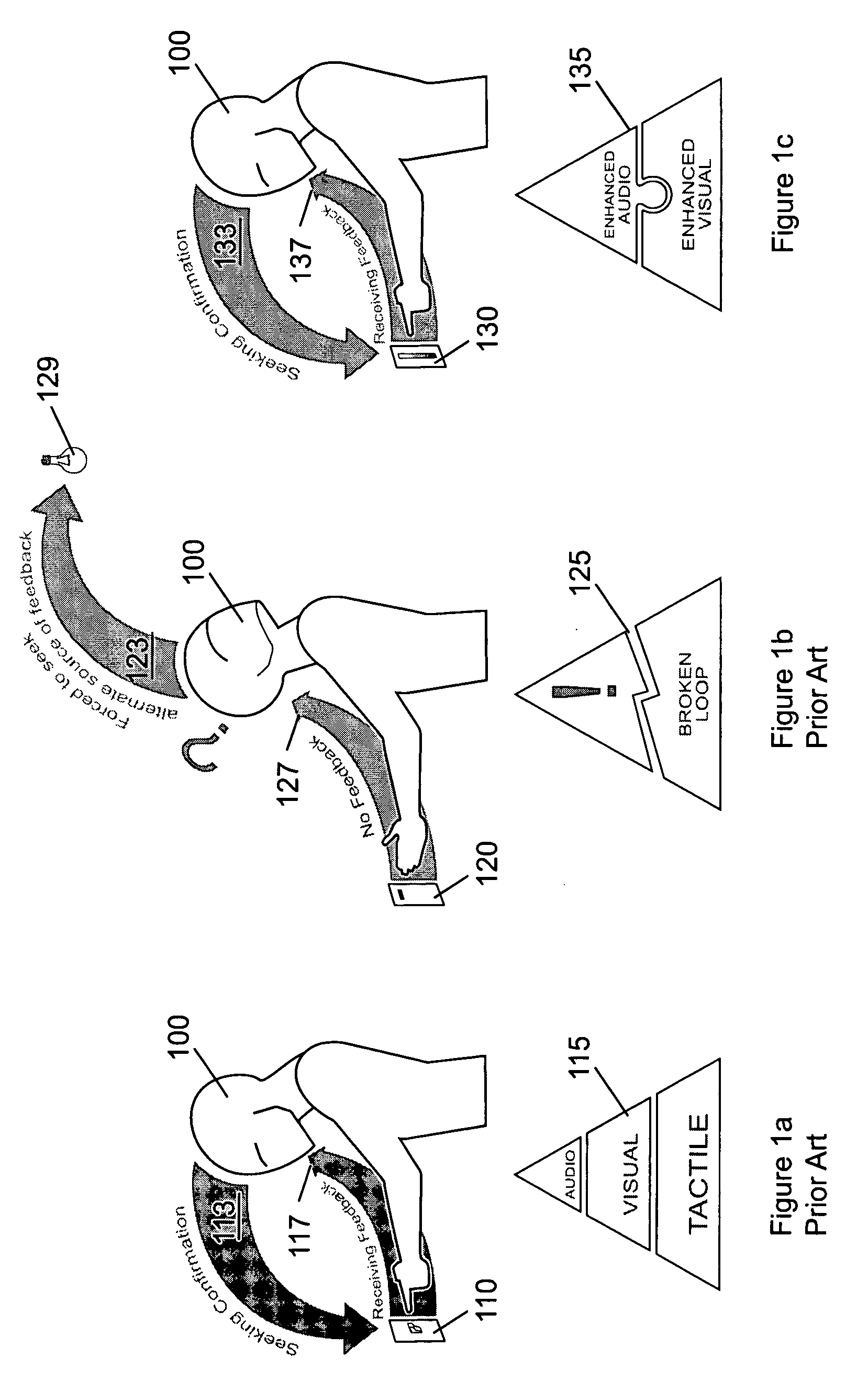
One of the problems associated with conventional non-contact switching mechanisms is the non-intuitive manner in which a user must determine the current electrical state of the switching mechanism and / or any output devices coupled to the switching mechanism.
However, the required location of the non-contact is often inconsistent with the location at which a user determines the current electrical state of the switching mechanism and / or the output device.
Unfortunately, this solution introduces further problems related to undesired or erroneous switching in which the noncontact switch changes electrical state in response to an unintended motion or sound.

Method used


Image

  • Sensory feedback systems for non-contact electrical switches
  • Sensory feedback systems for non-contact electrical switches
  • Sensory feedback systems for non-contact electrical switches

Examples


Embodiment Construction

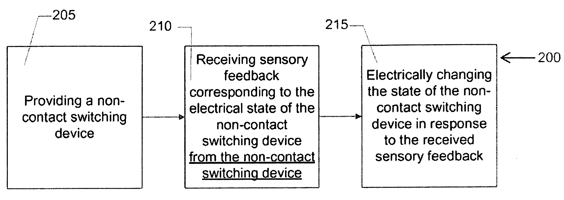
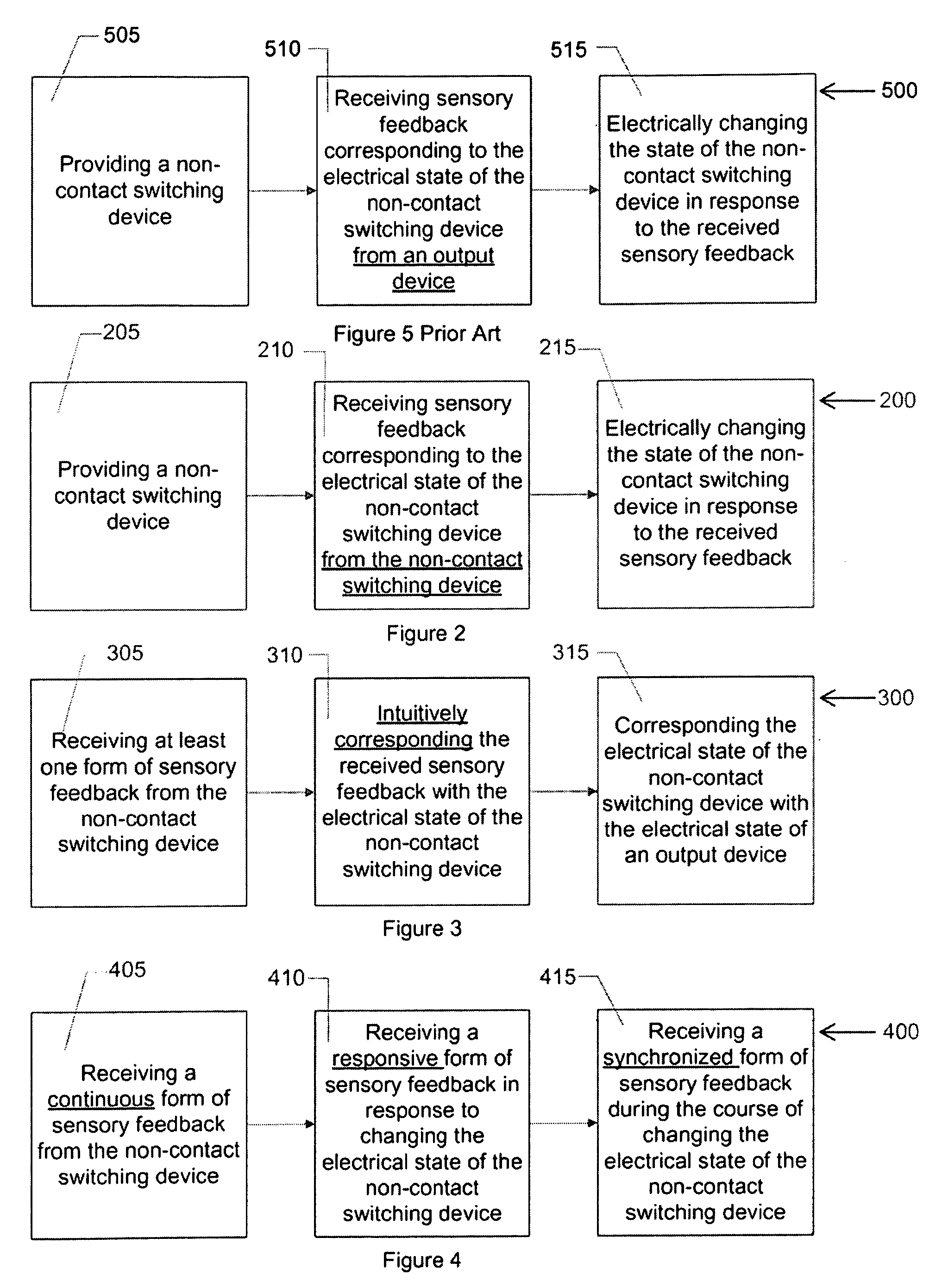
[0021]The present invention relates to non-contact electrical switching systems. One embodiment of the present invention relates to a non-contact electrical switching system including an electrical input, electrical output device, a non-contact electrical switching mechanism, and a sensory feedback system. The non-contact electrical switching system is connected to both the electrical input and electrical output device such that in an on state, the electrical output device is electrically connected to the electrical input and in an off state, the electrical output device is electrically disconnected from the electrical input. The non-contact electrical switching mechanism also includes a motion sensor to detect motion for the purpose of changing between the on and off state. The sensory feedback system is physically disposed on the non-contact electrical switching mechanism in proximity to the motion sensor. The sensory feedback system is configured to transmit sensory data correspo...


PUM


Abstract

The present invention relates to sensory feedback for non-contact electrical switching systems. Such systems may be used in conventional electrical circuits or in traditionally non-electrical switching systems, such as faucets. The non-contact electrical switching mechanism includes a motion sensor to detect motion for the purpose of changing between an on and an off state. The sensory feedback system is physically disposed on the non-contact electrical switching mechanism in proximity to the motion sensor and is configured to transmit sensory data corresponding to the current state of the non-contact switching mechanism. Sensory data is data which is received by one or more of the five human senses. The sensory data may include continuous, responsive, and / or synchronized sensory feedback. It will be appreciated that teachings of the present invention may be applied to other forms of human interface non-contact switching mechanisms such as those responding and / or detecting human generated sound, thoughts, etc.

Description

CROSS-REFERENCES TO RELATED APPLICATIONS[0001]This application claims priority on prior filed U.S. Provisional Application No. 60 / 870,239, filed on Friday, Dec. 15, 2006 and incorporates the same in its entirety herein.FIELD OF THE INVENTION[0002]The invention generally relates to non-contact electrical switching systems. In particular, the present invention relates to an improved sensory feedback system for noncontact electrical switches.BACKGROUND OF THE INVENTION[0003]Numerous non-contact or non-contact electrical switches are currently sold which enable users to change the electrical state of one or more devices without physically contacting the electrical device or switching mechanism. This type of switching mechanism has become preferable in many environments including unsanitary / ultra-sanitary environments, static free environments, high voltage devices, and moist electrical environments. Various technologies exist to enable the electrical switching without requiring physical...

Claims


Application Information

Patent Timeline
Patent Type & Authority Applications(United States)
IPC IPC(8): H01H31/00
CPCG06F3/017H01H2003/0293H03K17/96H03K2217/94052
Inventor PENG, ROBIN
Owner PENG ROBIN
Learn More